


14 B-CONTROL FADER BCF2000/ROTARY BCR2000 User Manual
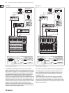
Important information about stand-alone modes:
With the wiring examples shown here, the parameter values of the controlled
devices can be shown on the B-CONTROL’s LEDs (parameter feedback). If this
is important to you, you will have to connect MIDI IN to the MIDI output of the
device you are controlling. Of course, the hardware unit you are using has to
support sending back the parameter values. If in doubt, check the user manual of
the equipment you are using.
Parameter feedback is enabled in all stand-alone modes. Other stand-alone
modes may cause undesirable MIDI loops. In stand-alone mode 3, the control
data of your B-CONTROL is routed to the MIDI output B without the
merge function.
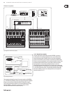
Your B-CONTROL can also control your computer via MIDI (without a USB
connection) as long as your computer features a MIDI interface. In this case,
all stand-alone modes can be used. To utilize parameter feedback, you should
still use the stand-alone mode 4. Alternatively, you can also use S-3 and connect
the computer via MIDI OUT B so that no MIDI feedback loop is created.
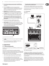
4.2 “Play” mode menu
The Play mode menu is the highest menu level in the B-CONTROL. Use it during
normal operation for real-time control of MIDI data.
Display:
After switching on the unit, the current system software version is briey
displayed. Value changes are shown when using one of the control elements,
provided that they have been activated.
Control elements:
You can use several keys, encoders and faders simultaneously and send their
MIDI data. The classication of MIDI data types is explained in chapter 4.4.
According to its assigned MIDI data type, each control element shows the current
parameter value in the corresponding LED or LED ring.
The position of the faders changes automatically as soon as you choose another
preset or during incoming parameter messages.
LED display:
The encoder LED ring displays or the status LEDs of the buttons change
automatically when running controller recordings in a sequencer, provided,
of course, all connections have been made correctly, the correct operating mode
is enabled and the software sequencer supports sending parameter values.
Button illumination varies according to the controller mode: if a button is in
“Toggle on” mode, the button LED illuminates as soon as the button is pressed.
Only when you press the button once again, the LED goes out. If a button is
in “Toggle o” mode, the corresponding LED will be lit only for the time the
button is pressed.
The performance of the control elements, the display and the LED displays can be
individually set up and is explained in chapter 4.3 “Programming”.
4.2.1 Selecting a preset
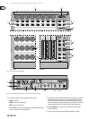
• Select a preset with the Preset button (8). The new preset number is
indicated in the display
• Alternatively, you may select a preset by pressing and holding down the
preset button while moving one of the push encoders
(1)
• As soon as you release the Preset button, the new preset is active
4.2.2 Copy / Store presets
• Press the STORE button to save a preset. The button LED starts to ash
• Select a memory number using the PRESET buttons or by holding down
one of the PRESET buttons while moving a push encoder at the same time.
The new preset number ashes in the display
• By pressing STORE again, the STORE LED and the display stop ashing
• If you want to overwrite the current preset, press the STORE button twice
(step 2 can be cancelled)
• Cancel the store procedure by pressing the EXIT button
We deliberately did not include an autostore function. That way,
you can assign a new MIDI control to a control element without changing the
currentpreset. If you want to restore a preset, just select another preset briey
and again return to editing. Now, the old data has been restored.
4.2.3 Copying encoder groups
With this function you are able to copy an entire encoder group within a preset.
This saves a lot of programming eort if all encoder groups within a preset
consist of the same basic functions (e.g. MIDI channel, CC number for turn and
push function).
Press the encoder group button of the group you want to copy.
• Press STORE; the STORE button LED ashes
• Now select the destination encoder group. The destination encoder button
LED ashes
• Press STORE again, the STORE button LED is no longer lit
• Cancel the store procedure at any time by pressing EXIT
◊ To permanently store encoder group settings, carry out the preset store
function as explained in chapter 4.2.2.
◊ To copy an encoder group into a different preset, you have to copy an
entire preset! After that, you can copy or rearrange the encoder groups
in the new preset as described above.
4.3 Programming
4.3.1 The LEARN function
The easiest way to assign MIDI functions to individual control elements is to
use the LEARN function. Here, the MIDI data is assigned remotely. For example,
MIDI data sent from a MIDI sequencer to your B-CONTROL is assigned to a control
element selected beforehand.
With LEARN, not only CC, NRPN and note commands can be received but almost
any type of MIDI data, including short SysEx strings.
• Press and hold the LEARN button while operating any control element.
This can be a fader (BCF2000 only), an encoder BCR2000 only),
a PUSH encoder, button, footswitch or sustain pedal (BCF2000 only).
The control element is shown in the display (e.g. E 24 or Fd 8)
◊ When using push encoders, select an encoder group beforehand.
In addition, you have to differentiate between turn and push function.
• Now, release the LEARN button. The B-CONTROL is waiting to receive
MIDI data
• Start transmitting MIDI data from your sequencer. As soon as the data is
received by the BCF2000 / BCR2000, it is shown in the display
• After correct data transmission, the display shows “GOOD” or “BAD” if wrong,
faulty or too extensive data has been sent
• To leave or cancel LEARN, press the EXIT button