


16 B-CONTROL FADER BCF2000/ROTARY BCR2000 User Manual
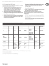
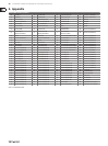
SWITCH TYPE CONTROLLERS (buttons, foot switches, push function of Push Encoders)
PUSH ENCODER
1 2 3 4 5 6 7 8
MIDI Data Type MIDI Send Channel Parameter Value 1 Value 2 Controller MODE Controller Option Display Value
PROGRAM CHANGE 1-16 O, Bank Select MSB O, Bank Select LSB
Fixed Program
Change-value:
O, 0 - 127
— —
Value indication:
On/O
CC
(Control Change)
1-16 CC-0-127 On-value: 0-127 O-Value: O, 0-127
Toggle On
Toggle O
Increment
In case of
'Increment' Steps:
-127...+127
Value indication:
On/O
NRPN
(Non Registered
Parameter Number)
1-16
NRPN Parameter
Number
On-value: 0-12 O-Value: O, 0-127
Toggle On
Toggle O
Increment
In case of
'Increment' Steps:
-127...+127
Value indication:
On/O
NOTE (MIDI notes) 1-16
MIDI Note Number:
0-127
Fixed velocity-value:
0-127
—
Toggle On
Toggle O
—
Value indication:
On/O
AFTER TOUCH 1-16
Key number
0-127, ALL
(All = Channel
Aftertouch
Min. value:
0-127
Max. value:
0-127
—
In case of
'Increment' Steps:
-127...+127
Value indication:
On/O
MMC
(MIDI machine
control)
MIDI Device number:
0-126, ALL
Select:
Play, Pause, Stop,
Fwd, Rew
Locate
Punch In
Punch Out
If Frame rate not O
Frame Rate:
O
24
25
30
30d
(drop frame)
—
Value indication:
On/O
Locate position time
(1st part): hh:mm
Locate position
always sent rst
(before MMC-
command)
Locate positiontime
(2nd part): ss:
(Frames) Locate
position always sent
rst (before MMC-
command)
GS/XG 1-16
Select GS/XG-Main
Control-parameter
with clear text
indication
On-value: 0-127 O-value: O, 0-127
Toggle On
Toggle O
—
Value indication:
On/O
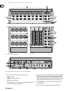
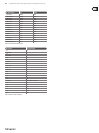
Tab. 4.2: Assignment of the push encoders in EDIT mode (CONTINUOUS types)
Table explanation:
All settings in the EDIT mode are made by turning the push encoders.
Pressing the push encoder displays its current value. In addition, the setting
options depend on whether the selected control element is a SWITCH type or
CONTINUOUS type.
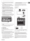
In the EDIT mode, Push Encoder 1 selects (by turning) the type of command
assigned to a control element.
With Push Encoder 2, select a MIDI channel through which that control
element’s data is sent.
Push Encoders 3 - 5 set parameters and values for the selected MIDI type.
They vary depending on the MIDI function. More details about this subject can be
found later in this chapter.
Push Encoder 6 (Controller Mode) selects how the previously selected control
element behaves, depending on whether it is a SWITCH or a CONTINUOUS type
CONTINUOUS-type elements:
CONTINUOUS-type element controls are divided into “Absolute,” “Absolute
(14 bit),” “Relative 1” (2nd complement), “Relative 2” (binary oset), “Relative 3”
(MSB, most signicant bit), “Relative 1 (14 bit),” “Relative 2 (14 bit),” “Relative 3
(14 bit)” and “Increment/Decrement.” Absolute means absolute data values
although jumps may occur when changing values. With Relative, the current
parameter value is continued independently from the position of the control.
Absolute (14-Bit) or one of the Relative (14-Bit) modes are standard modes
for value changes at NRPNs with high resolution. This is necessary with some
software mixers if more than 128 steps are needed. Increment / Decrement
serves as a step-by-step increase or decrease of values by using the Data
Increment / Decrement commands (see list 5.1 in the appendix).
◊ The classic controler mode for most applications is “absolute”.
All other modes have to be supported by the MIDI software or the
device to be controlled.
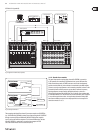
Using Push Encoder 7, you can adjust how control elements display information.
Depending on whether you are dealing with an encoder, push encoder, fader or
foot pedal, there are dierent options available:
LED display of the push encoders:
OFF The LED circle remains o.
1d (1 digit): Only one LED lights up (standard setting).
1d- The LED circle operates similar to “1d”, but when the value is 0,
no LED lights up.
2d The display of the LED circles occurs in two stages. If you slowly turn the
encoder from left to right, at rst only one LED lights up, and then the
next LED lights up while the previous LED goes out, and so on. This way,
even the slightest value changes can be accurately represented.
2d- Just like “2d”, but when the value is 0, no LED lights up.
Bar Bar display: when the value is changed, all LEDs light up successively
(for volume etc.).
Bar- Just like bar display, but when the value is 0, no LED lights up.
Sprd Spread: When the value is 0, the upper middle LED lights up; when the
value is increased, the LED circle gradually lights up in both directions
(left and right).
Pan In the middle position (value = 64), only the upper middle LED is on.
With lower values, the LED circle lights up toward the left; with higher
values, the LED circle lights up toward the right (panorama adjustment).