


18 B-CONTROL FADER BCF2000/ROTARY BCR2000 User Manual
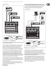
MMC:
MIDI Machine Control data is only assignable to button elements.
Encoder 4 (Value 1) sets “Locate Time” hour and minute values, while encoder 5
(Value 2) sets seconds and frames. The Locate Position is always sent before the
MMC command. We therefore have the following logic-switching sequence:
If the “Locate” parameter has been selected, the sequencer or hard drive recorder
always jumps to the set position. If “Play” has been selected as the parameter
(for a button), the sequencer always starts from the set locator point as soon
as the button is pressed. “Rewind” always begins at the chosen locator point.
Select the frame rate with encoder 6: 24, 25, 30 (non-drop), 30d (drop frame)
or “o” (in this case only the MMC message is sent, without any information of
the locate position).
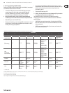
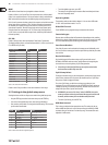
GS / XG:
Encoder 3 directly selects the most important “Main Control” parameters.
The display indicates them as a (shortened) text (table 4.2). In this case, these are
CCs or NRPNs (no SysEx data).
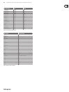
GS / XG-Parameter Type Display
Filter Cuto NRPN CUTF
Filter Resonance NRPN RESO
Vibrato Rate NRPN RATE
Vibrato Depth NRPN DEPT
Vibrato Delay NRPN DLY
EG Attack NRPN ATC
EG Decay NRPN DCY
EG Release NRPN RELS
Modulation CC 1 MODU
Portamento Time CC 5 PORT
Volume CC 7 VOL
Pan CC 10 PAN
Reverb Send CC 91 REVB
Chorus Send CC 93 CRS
Delay / Variation Send CC 94 VARS
Table 4.3: GS / XG Parameter Main Controls
Encoders 4 and 5 let you conne or invert each controllers’ value range.
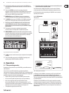
4.5 Settings in the global setup menu
Settings that have an eect on all presets are made in the global setup menu.
• Keep the EDIT key pressed and at the same time press the STORE key
• You are now in the global setup menu, and can let go of both keys
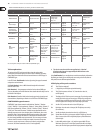
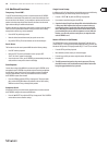
• Now, turn the push encoders 1 to 8 to get the desired setting. This is how the
push encoders are allocated
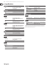
Encoder Function Select
1 Operating Mode U-1 ... U-4, S-1 ... S-4
2 Global RX Channel O, 1 ... 16
3 Footswitch Auto / Normal / Inverted
4 Start-Preset 1 ... 32, Last
5 Device ID 1 ... 16
6 SysEx Dump Single/All
7 — —
8 MIDI Data Interval (ms)
Table 4.4: Push encoder allocation in global setup menu
• To exit the global setup menu, press EXIT
• The settings in the global setup menu take eect immediately and do not
have to be separately stored
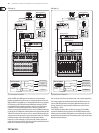
Operating Mode:
The operating modes are described in chapter 4.1. You can select USB modes
U-1 to U-4 and stand-alone modes S-1 to S-4.
Global RX Channel:
The B-CONTROL receives program change commands on this channel.
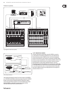
Footswitch type:
Because there are dierent kinds of footswitches (depending on their switching
behavior), the polarity of the footswitch connector can be set (normal / inverted),
or it can be automatically detected during power startup (auto recognition).
Start Preset Number:
Each of the 32 presets can be selected as the startup preset. Additionally, with
the “Last” function, at startup you have the option to always load the preset that
was used last.
Device ID Number:
You should change the ID number settings only if you work with several
BCF2000s or BCR2000s at the same time, and problems with recognizing the
correct device start occurring during a SysEx Dump procedure.
◊ Please keep in mind that SysEx Dumps can only be received at the
device number to which they were sent!
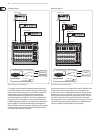
SysEx Dump Select:
Turning push encoder 6 lets you select between the current preset (single) or the
entire memory contents of the 32 presets (all) should be sent as a SysEx dump.
One press on encoder 6 triggers the dump.
To receive a SysEx dump, you don’t have to change any settings on your
equipment. If you send a single preset to the B-CONTROL, the data is written to
a temporary memory; to be stored permanently, the data has to be stored on a
storage slot of your choice (preset store function).
◊ WARNING: If you send an “ALL-Dump” to the B-CONTROL, the entire
memory contents are directly overwritten! No request to confirm will
be made, and the memory has no redundant safety function!
• To cancel a SysEx dump, press the EXIT key
MIDI Data Interval:
This is where you adjust the data transmission rate. This setting only has an
eect on MIDI data packs such as SysEx dumps and not on controlling of MIDI
commands (they are carried out in real time anyway). The transmission rate is
adjustable in milliseconds.