


7 B-CONTROL FADER BCF2000/ROTARY BCR2000 User Manual
Note On and Note O messages have the following
data format:
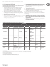
Status Byte Data Byte 1 Data Byte 2
Note O &8n (n = channel #) Note # Velocity
Note On &9n (n = channel #) Note # Velocity
Table 2.1: Data format of Note On and Note O messages
The value range for channel numbers is between 1 and 16; for data bytes it
is 0 to 127. Even though Note O messages are not really used by keyboarders
anymore, the B-CONTROLs support sending this status information.
Velocity corresponds to the key pressure, and therefore to the volume of a
touch-sensitive keyboard (piano). Since the B-CONTROL does not feature
touch-sensitive keys, the velocity value is transmitted with a xed value that can
be set during programming.
◊ A note command can only be assigned to keys, footswitches and push
functions of the encoder.
Control Change (CC):
Control Change Messages are some of the most “powerful” MIDI messages.
Using them, a vast number of parameters and functions can be recalled and
automated. Individual control elements (faders, rotary dials, keys etc.) can be
assigned to CC messages on your B-CONTROL. Because not only keys but also
faders and rotary dials can be used, control values can be controlled in real time
either statically or dynamically. A list with the standard controller numbers can
be found in this user manual’s appendix.
NRPN:
Additionally, controllers that have no standardized assignment can also be
used, and can therefore be assigned according to no predetermined rule.
These controllers are called NRPNs (Non-Registered Parameter Numbers).
NRPNs are further subdivided into MSB (Most Signicant Byte) and LSB
(Least Signicant Byte) in order to achieve a higher resolution. A lower resolution
is particularly easy to observe during fader movement of a mixer, in which 7-bit
(= 128 values) jumps in the signal level can be heard. By subdividing NRPNs
into MSB and LSB, you can achieve 14-bit resolution of faders and rotary dials,
which means that the movement of a fader is divided into more than 16,000
steps (214)! In addition to NRPNs, there are also RPNs (Registered Parameter
Numbers). RPN commands are dened as GM (general MIDI), GS (Roland) and
XG (Yamaha) MIDI standards.
Pitch Bend:
The pitch-bend wheel of a keyboard is used for tone modulation and has its own
commands in the MIDI format.
After Touch:
MIDI keyboards featuring After Touch can respond to varying key pressure even
after you release the key (i.e. after the keystroke is over) and can send this data
via MIDI. This function either reacts key-specic (key pressure) or it reacts to all
notes at the same time (channel pressure).
MIDI Machine Control (MMC):
With MIDI Machine Control, you can assign transport functions of a sequencer or
drum computer (e.g. start, stop, FFW / RWD) and locator points to individual keys
with a permanently adjustable time position (locate, punch in / out points).
Program Change Messages and MIDI Bank Select:
Program change messages are used to recall programs / presets in MIDI devices
connected to your B-CONTROL. 128 program numbers can be recalled. For devices
with more than 128 presets, use the bank select function, which lets you select a
storage bank before sending a program change.
Running Status:
Because the MIDI interface is a serial data transmission format (meaning that
its data is transmitted as a succession of individual data segments), it became
apparent very quickly that it may not be fast enough. To avoid perceptible delays
in the output of MIDI data, Running Status was designed. It suppresses the
transmission of the status byte when the same MIDI messages are transmitted
in succession. This means that, for example, during a continuous change of
the data byte of a controller (e.g. volume), the status byte is only sent once.
The only thing that is transmitted are the changes in the data byte. This goes on
until another status byte is sent. 8 bits are saved for each message sent.
SysEx Dump:
System-Exclusive data refer to a function that makes transmission of nonspecic
data via MIDI possible. This is often used for reading out memory contents and
storing them externally.
The status byte notes the data type (SysEx); the rst three data bytes are a
manufacturer ID, so that when you have a large MIDI network, you can still “talk”
to the correct MIDI device.
To make using several identical B-CONTROLs at the same time possible, you can
assign a device number (device ID) in the global setup menu to each B-CONTROL,
which assures that only the correct device receives the data intended for it.
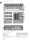
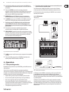
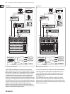
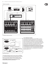
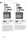
3. Control Elements and
Connections
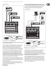
In this chapter, we will describe various control elements of your B-CONTROL.
All controls and connectors are explained in detail, and we’ll give you useful tips
on how to use them.
(1) The 8 innitely variable PUSH ENCODERS are used to send MIDI data.
They have two functions (turn and press) that can be assigned to dierent
MIDI commands.
(2) Each of these 16 KEYS can send one MIDI command.
(3) The four-digit LED display indicates the current operating software version
briey during startup. After that, it shows the selected preset number.
When in play mode, activating one of the control elements indicates
value changes on the LED in real time. When in programming mode,
it indicates the type of MIDI commands, program / channel numbers and
parameter values.
(4) Using the ENCODER GROUP keys, four so-called encoder groups per preset
can be recalled, so that eight PUSH encoders for a total of 64 dierent MIDI
functions are at your disposal.
(5) These LEDs indicate the following:
MIDI IN, OUT A and OUT B illuminate if MIDI data ows through the
respective connectors.
USB Mode illuminates if a USB connection to a computer is active
(your computer must be on).
The FOOT SW LEDs illuminate if the footswitch is pressed.
FOOT CTRL LED (BCF2000 only) illuminates when the footcontroller is
actuated (MIDI data is sent).