


9 B-CONTROL FADER BCF2000/ROTARY BCR2000 User Manual
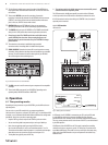
(10) The 24 innitely variable rotary controls (encoders) of the BCR2000 can
be programmed to send MIDI control commands. The LED circle show the
current value.
(11) These are the SWITCH connectors for connecting a footswitch.
Its polarity is automatically detected. On the BCR2000, the rst connector
(SWITCH 1) can also be used to connect a double footswitch with stereo
jacks. In this case, SWITCH 2 must remain unused.
(12) CONTROLLER connector (BCF2000 only). Here, you can connect an
expression pedal that can be used for controlling assignable MIDI data.
(13) The POWER switch turns your B-CONTROL on. The POWER switch should
always be in its “O” position when connecting the unit to the mains.
◊ Please keep in mind: The POWER switch does not fully disconnect
your B-CONTROL from the mains. Always unplug the power cord
from the mains if you don’t intend to use your B-CONTROL for longer
periods of time.
(14) The connection to the mains is established using a standard
connectionsocket. A matching cable is included in the shipment.
(15) SERIAL NUMBER. Please take the time to ll out and return the warranty
card within 14 days after the date of purchase to benet from our extended
warranty. The serial number is located on the top side of your REV2496.
You can also register online at behringer.com.
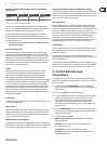
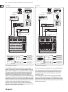
BCR2000
MIDI
(11)
Fig. 3.3: The footswitch connectors on the BCR2000
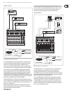
(16) The USB connector is used for connecting to a computer with a compatible
USB input.
(17) These are the MIDI connectors of your B-CONTROL. Depending on the
operating mode, MIDI OUT B doubles as MIDI THRU.
4. Operation
4.1 The operating modes
Depending on how you want to use your B-CONTROL, you should rst select an
operating mode.
You can use it as a pure USB controller for your computer applications
(software mixers, sequencers, soft synths, VST-eects etc.), as a stand-alone MIDI
controller, or as a combination of both with dierent MIDI interface conguration
possibilities. Here is how you select an operating mode:
• Keep the EDIT key pressed, and press the STORE key at the same time
• You are now in the global setup menu and you can let go of both keys
• Now, select an operating mode by turning the PUSH encoder 1.
You can select USB modes U-1 to U-4 and stand-alone modes S-1 to S-4.
The modes are described in detail in chapter 4.1.1 and further, and examples
about their use are also given there. Please see also chapter 4.3.3
• To exit global setup, please press the EXIT key
◊ The settings made in the global setup menu are automatically stored
and do not have to be separately saved.
The USB connection is briey interrupted if you switch within a USB mode,
or when you switch from a USB mode to a stand-alone mode and vice versa.
If a USB connection is made or lost while your B-CONTROL is on, the selected
operating mode is retained.
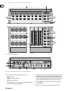
4.1.1 USB modes
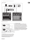
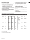
USB mode U-1:
BCF/BCR2000
Parameter
Feedback
to Computer
from Computer
USB
MIDI IN
MIDI OUT A
MIDI OUT B/
THRU
B-CONTROL
MIDI Data Send
Computer
Software Sequencer
push
Software Mixer
move/
fade
turn
push
Software Synthesizer
move/
fade
turn
push
OUT A
OUT B/THRU
MIDI IN
Fig. 4.1: Routing and use in USB mode 1
In USB mode 1, the B-CONTROL is connected to your PC by using a USB cable.
It sends MIDI data and receives parameter feedback from the computer,
provided that the music software you are controlling supports these functions.
This way, current parameter values can be shown on the LED, or can be indicated
by the fader position.
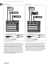
All MIDI ports of the B-CONTROL are o. This mode is optimal for controlling
software tools (mixers, sequencers, synths, VST-eects etc.) if you don’t need
any additional MIDI ports. This mode is also very useful if you are already using
other multi-channel MIDI interfaces on your computer and can’t address any
additional ones.