


24
attack time, so that the increasing high frequency transients pass through the compressor unhindered before
the compressor takes effect.
The AUTOCOM PRO MDX1400 offers a solution to this problem that is by much more elegant. The SC Filter
switch allows you to activate a high-pass filter in the control signal path of the compressor. This filter makes
sure that midrange and treble range frequencies are taken into account to a greater extent, and that a low-
frequency signal triggers less compression than a midrange/treble signal of comparable level. A major advan-
tage of this design can be seen in the fact that the frequency response of the overall signal is not modified
below the threshold adjusted with the Threshold control.
In pop music the dynamics of both kick drum and bass guitar are usually processed individually. The side-
chain filter is therefore ideally suited to apply overall compression in the mix-down, to compress the music
while increasing its loudness, but without having to accept the drawbacks described above.
5.4 Dynamic Enhancer Section
In addition to the above mentioned method with the sidechain filter the AUTOCOM PRO offers another alterna-
tive solution: the Dynamic Enhancer. It eliminates the problems without creating any additional negative side
effects. As the signal level rises towards the threshold point where compression will occur, high frequency
enhancement is added at the same degree to which the input signal is compressed. The AUTOCOM PRO
accurately tracks the amount of compression in order to compensate with the same amount of dynamic
enhancement, even if there are heavy signal variations. When there is no compression taking place, the
Dynamic Enhancer is inoperative and therefore, no additional noise or signal equalization is added to the
signal. For more versatility, a PROCESS control allows you to control the available amount of dynamic en-
hancement. The range lies between Off and 6.
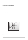
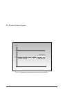
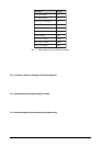
The typical dynamic enhancement function is shown in the following figures:
0 dB
-20 dB
No Gain Reduction
20 dB Gain Reduction Without Enhancer
With Enhancer
Frequency
Output
Fig. 5.3: The frequency response with and without dynamic enhancer
5.APPLICATIONS