


10
EURORACK MX2004A
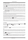
2.5 Insert
Insert points are useful for adding dynamic processing or equalization to a channel or the mix. Unlike reverbs
etc., which are usually added to the dry signal, dynamic processing is normally applied across an entire
signal. Here an aux send would be inappropriate. Instead the signal is intercepted somewhere along the
channel, fed through the dynamics processor and/or EQ, then returned to the console at the same point where
it left. The insert point is normalized, i.e. the signal is only interrupted when a jack is plugged into it.
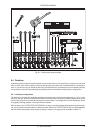
3. STEREO INPUT CHANNEL
Each stereo channel comes with two balanced line level inputs on 1/4" TRS connectors, for left and right
signals. When only the left input is connected, the channel operates in mono.
3.1 Input level setting
The stereo inputs are designed for any line level signal. Most line level sources such as MIDI instruments and
FX units will have their own output level control. Those that don’t, for example CD players, all have an output
level within the scope of the MX2004A. When the channel and master fader are set to unity gain the meters
should read between -4 and +7 dB. Remember that there is 15 dB gain on both the channel as well as master
fader.
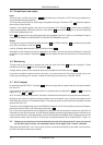
3.2 Equalizer
The stereo input channels are fitted with 4-band EQ. The upper and lower shelving controls have their frequen-
cies fixed at 12 kHz and 80 Hz. The peaking high midrange and low midrange / are fixed at
3 kHz and 500 Hz respectively. A stereo equalizer is generally preferable to using two mono equalizers when
EQ-ing a stereo signal, as often discrepancies between left and right settings can occur.
3.3 Aux sends
These are the same as for mono channels (see 2.3). Note that a mono sum is taken from the stereo input.
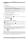
3.4 Routing
The only difference here from the mono channel described in 2.4 is in the implementation of the balance control
.
When a channel is run in stereo, this control functions as a balance control, determining the relative balance of
the left and right channel signals being sent to the left and right main mix buses. For example, with the balance
control turned fully clockwise, only the right portion of the channel’s stereo signal will be routed to the main
mix.
Balance also determines the relative amount of left and right channel signals being sent to buses 3 and 4
respectively when Mute/Alt 3-4 is engaged.
4. MAIN SECTION
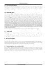
4.1 Aux sends
Master aux send levels are determined by and . These controls have a centre detent indicating unity
gain. Don’t worry if your effects unit has no input gain control—you have a further +15 dB available from these
outputs.
3. STEREO INPUT CHANNEL