


11
EURORACK MX2004A
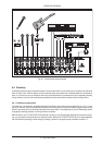
4.2 Stereo aux returns
There are two additional stereo line inputs (aux returns 1 and 2) on your MX2004A. Aux returns 1 is perma-
nently assigned to the main mix. If you connect a jack to the left socket only, the aux return 1 operates in
mono. Aux return 2 can be switched between the main mix and the cue feed (aux send 1) via a switch
FX TO AUX 1 . This enables you to provide a wet (signal with effect i.e. reverb) cue mix for the headphones
or foldback speakers.
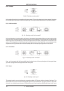
If no connection is made to aux return 2, the signal is “normalled” (connected directly) to aux return 1. Depress-
ing the FX TO AUX 1 switch will then feed the signal from aux return 1 into the cue feed (aux send 1) and can
be controlled in level independently with aux return 2. This feature is primarily useful when you are using one
effect for the main mix and for the foldback speakers.
+ When using aux send 1 as a second (pre-fader) effects send and aux return 2 as the effect
input, do not engage FX TO AUX 1 switch. The connection from aux return 2 to aux send 1
could cause feedback.
However, there are exceptions: For instance if you deliberately want to send one effect into another, e.g. delay
into chorus etc.
The aux returns are multifunctional. They may be used for returning the outputs of effect units. You can use
them as tape returns from a multitrack recorder. They may also be used as extra instrument inputs, especially
if your MIDI keyboard or rack supplies a pre-mixed stereo signal.
Certain stereo effects produce a perceived imbalance between the left and right channel levels. To correct for
this you will have to bring your stereo effect back on a stereo channel, which has a balance control.
When applying short left and right delays, the shortest one will always seem loudest. When pitch shifting up
and down in wide stereo to thicken a sound, the signal shifted upwards will seem louder than one that goes
down. In both cases use the balance control to compensate.
When performing any stereo imaging exercise, don’t just rely on the control room monitors. Get a pair of
headphones and listen in stereo and in reverse stereo, just in case you have any significant hearing discrepan-
cies.
Sometimes an engineer wants to narrow the stereo width of a reverb field. To do this you will have to come back
on two mono channels to get independent pan for the left and right signals.
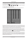
4.3 Metering
Main mix/PFL/solo level is displayed on a pair of highly-accurate 13-segment bargraph peak meters .
Additional LEDs indicate POWER ON , +48 V phantom power present , and whether the mono Pre-
Fader-Listen bus or the stereo solo bus is engaged.
4.4 Solo function
The CHANNEL MODE switch determines whether Solo-In-Place or Pre-Fader-Listen is assigned to the
channel Solo buttons.
Solo
Solo is the preferred method for auditioning an isolated signal, or group of signals. Whenever a PFL/SOLO
button is pressed, all unselected channels are muted in the monitors. Stereo panning is maintained. The solo
bus is derived from the output of the channel pans, aux sends and stereo line inputs. It is always post-fader.
PFL
Pressing once disengages the stereo solo bus, and replaces it with a separate mono PFL (Pre-Fader-
Listen) bus. All solo signals are reconfigured to PFL. PFL should always be used for gain-setting (see also the
essential chapter 5 “SETTING UP”).
The L/R meters follow whatever source is being auditioned (the meters won’t make much sense if more
than one source is selected!). Selecting PFL/solo does not affect the signal from the L/R recording outputs.
Just as well, or every time you wanted to do a quick Solo check during a mix, you’d have to start again!
4. MAIN SECTION