


20
EURORACK MX2004A
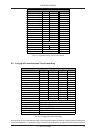
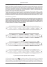
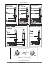
thus allows for recording both to the DAT recorder and the tape deck, simply by patching it accordingly. Modules 19
& 20 (tape deck) are open, because it does not make sense connecting the inputs and outputs of the tape deck. 21
& 22 are normalled and route the DAT recorder outputs to the 2-track inputs of the mixing console. So it always is
possible to control the recorded data on the 2-track from the mixing console. The CD player and the HiFi system are
connected to modules 23 & 24, which are open, because they only serve as a source.
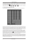
In patchbay
2
the first 16 modules are normalled (1 through 8 IN could also be used to connect the corre-
sponding monitor inputs—if the console has a separate monitor section). MIDI devices such as samplers,
expanders, keyboards, etc. are usually set up in every corner of the room. To make the cabling better struc-
tured we route these units to modules 9 through 16. This allows further workmanship of the MIDI devices at the
mixing console. Modules 17 through 20 are normalled and have the FX inputs and the aux sends connected, 21
through 24 are also normalled and are patched to the two stereo aux returns with the FX outputs.
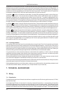
In patchbay
3
, modules 1 through 16 are for the channel insert. These modules are half-normalled, so that you
have an additional route for the channel signals. The same applies to the insert paths of the subgroups and the
master output. The headphones amp is connected to 23 & 24, which are normalled and connected to the control
room outputs of the mixing console. Of course, you can also use pre-fader aux paths for the headphones mix.
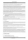
Patchbay
4
manages the dynamics and frequency-processing devices in an open configuration (modules 1
through 16). Multigates and Compressors should be used here, in particular. Modules 17 through 24 are used to
provide a “parallel split”, i.e. two modules are patched to each other on the rear with one patch cord, so that you
can split up a signal applied on the front panel to several destinations. These modules have a parallel configuration.
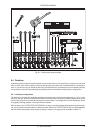
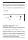
It should be noted that patchbays should be placed one below the other in such a way that the patch cords
won’t hang all over the patchbays. In our example you don’t have to span great distances, for instance, to patch
the dynamics and EQ’s to the insert paths.
6.4.7 Looming problems
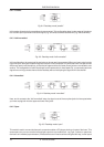
Loom wiring is an art unto itself, and it is worth taking time out to get it right. First off, it is important to avoid earth
loops (a looped wire acts an aerial, picking up hum and electromagnetic radiation). Think of a tree. Every part of
that tree is connected to every other part, but only by one route. That’s how the total earth picture for your entire
studio should look. Don’t take the earth off your power cable plug to reduce audible 50 Hz mains hum. Rather you
should be looking at disconnecting the signal screen somewhere (one or several audio cables).
It is good practice to ensure that all screens are commoned at the patchbay, in which case all unearthed
equipment would pick up earth from this point via a single screen (more than one route = an earth loop), while
mains-earthed equipment would have all screens cut at the equipment end.
Some quality equipment has an independent signal and mains earth. In this case at least one screen should
carry earth to the equipment. Sometimes the only way to find out is “suck and see”.
Take care to ensure that using the patchbay does not disturb the studio’s earth architecture. Always use short
as possible patch leads with the screen connected at both ends.
Having designed mains hum out of the system, make up your cable looms from the patchbays outwards, and
use cable ties, flexible sheaths, multicores, etc. to keep the back of your racks tidy.
7. TECHNICAL BACKGROUND
7.1 Mixing
7.1.1 Equalization
Few people buying a mixer will need to be told how an equalizer works. But how to get the best out of it? Well,
that’s another story.
In the beginning EQ was an instrument for removing unwanted frequencies, or compensating for imperfect
microphone response curves, or bumps in a studio’s acoustic. It was a corrective device. Tamla Motown turned
that notion upside down in the sixties with the novel idea that you try to find for each instrument a characteristic
frequency not shared by the other instruments in the mix. Then you whack up its gain. This makes individual
7. TECHNICAL BACKGROUND