


iDR-8 User Guide 11
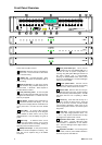
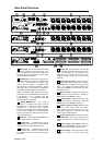
Physical inputs and outputs These are the
hardware audio connections including XLRs,
digital expanders, headphones and monitor.
Input and output channels These are
processing channels. The input channels can be
sourced from any physical input. The physical
outputs can be sourced from any output channel.
The input and output channels are interconnected
through the crosspoint matrix. They are routed to
and from the physical connections via the source
patchbays. The iDR-8 has enough processing
built in for 16 input and 16 output channels when
in 48kHz mode. The iDR-in and iDR-out
expanders simply convert the connected
analogue audio into digital signals to feed the
iDR-8 where they access the 16x16 matrix. The
expanders are not available when in 96kHz mode.
Analog inputs The iDR-8 and iDR-in each have
8 analogue XLR inputs. These feed high grade
balanced mic preamp circuits. They accept a
wide range of microphone and line level signals.
Gain, pad and 48V phantom power switching are
controlled using the iDR System Manager
software so they can be part of the recallable
patch system. There are no trimmers or internal
adjustments needed.
Soft limiter The output of each preamp is fed
through an analogue limiter just before the ADC.
The limiter uses an opto device to prevent
excessively high input signals overloading the
converters and causing harsh distortion.
Threshold is -4dBFS. The limiter can be switched
in or out under software control.
Analog outputs The iDR-8 and iDR-out each
have 8 analogue XLR line outputs. These are
balanced and can produce up to +18dBu
maximum signal level.
ADC and DAC converters These convert the
analogue signals into digital (ADC) and processed
digital signals into analogue (DAC). High grade
24bit converters are used.
Expander input and output 8 Channels of audio
is communicated between iDR units using these
RJ45 ports. The digital signals are fed to and from
the associated virtual patchbays. Routing the
signals through the patchbays in this way
provides the flexibility for common sources to be
networked between multiple iDR units using CAT5
cable.
Monitor inputs and outputs A front panel stereo
headphones output is provided. Balanced line
level L and R inputs and outputs are available on
the rear panel. The inputs feed the active monitor
bus and can also be routed into the source
patchbay. The outputs are fed from a patchbay
which gets its source from the active monitor bus
or any output channel. In this way these
connections can be used either as a monitor
system or as channels in their own right.
Signal generator Provides another selectable
source feeding the input channels through the
patchbay. Variable frequency sine wave, pink
noise, white noise or 1/3 octave band pass noise
can be selected. These can be used for system
line up and testing. The level is controlled using
the fader and mute function.
Source patchbays These connect the physical
inputs and outputs to the channels so providing a
flexible ‘virtual patchbay’ routing system. One
physical input can feed more than one input
channel. One output channel can feed more than
one physical output. Note that, as with any
physical patchbay, you cannot route two sources
into one channel, or two channels into one output.
Mix matrix This is the routing ‘heart’ of the
system fed by all 16 input channels, and feeding
all 16 output channels. It is known as a 16x16
crosspoint matrix. The signal can be switched or
have its level independently controlled at any
point. It is the matrix which provides the key to
independent multi-source zone routing and level
control.
+
-
+
-
+
-
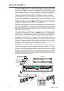
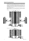
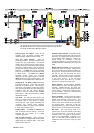
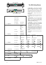
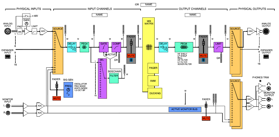
The channel architecture illustrating the processing blocks is shown above.
For detailed instructions on using these please refer to the Help file which
comes with the iDR System Manager software.