34 IDR-8 User Guide
Adding the iDR-switch Expander
The iDR-switch is an add-on control expander for the iDR-8 audio mix processor. It provides an additional 24 switch
closure control inputs and 16 logic control outputs in a 1U high rack or desk mount case. Up to three units can be
connected providing up to 72 additional switch and 48 additional logic controls. These can be custom wired by the
installer to allow external equipment to control pre-determined mixer functions, or the mixer to control external
equipment. Typical applications include room wall plates for local volume control and source selection, patch recall,
logic control, automatic control of room dividers, projection screens, media players, lamps and other equipment.
The inputs and outputs are opto-isolated to avoid problems with equipment interaction. Grounding the switch inputs
using simple contact closures triggers the programmed function. The logic outputs are open collector and can be
wired to use the internal reference voltage or an external power supply. These typically drive LED indicators, filament
bulbs, relays and circuit logic. Wiring the interface should be carried out by competent installation personnel. The
switch and output functions are easily programmed using the iDR System Manager software.
The iDR-8 communicates with the iDR-switch via the DR-Link port. This uses the proprietary Allen & Heath DR-Link
protocol. A standard 2 metre CAT5 STP cable is provided. However, you can use a cable up to 300 metres long
letting you position the unit closer to the local switch wiring. A pass through connection lets you network up to three
units by daisy chaining them.
Make sure you have read the Important Safety
Instructions printed earlier. Also check that your local
mains supply is compatible with that printed on the rear
panel of the unit. Ensure that the correct mains lead with
moulded plug and IEC connector has been supplied. For
your own safety and optimum performance make sure the
system is correctly grounded.
Turning the expander on or off Turn the unit on
by pressing the rear panel power ON/OFF switch. The power
LED lights up. The link LED lights if the DR-Link connection is
established with the iDR-8. The iDR System Manager detects
the presence of connected iDR-switch units.
Checking for iDR-switch expanders You can
check to see how many iDR-switch units are connected and
working from within iDR System Manager by opening up the
Soft LEDs or Soft Keys windows.
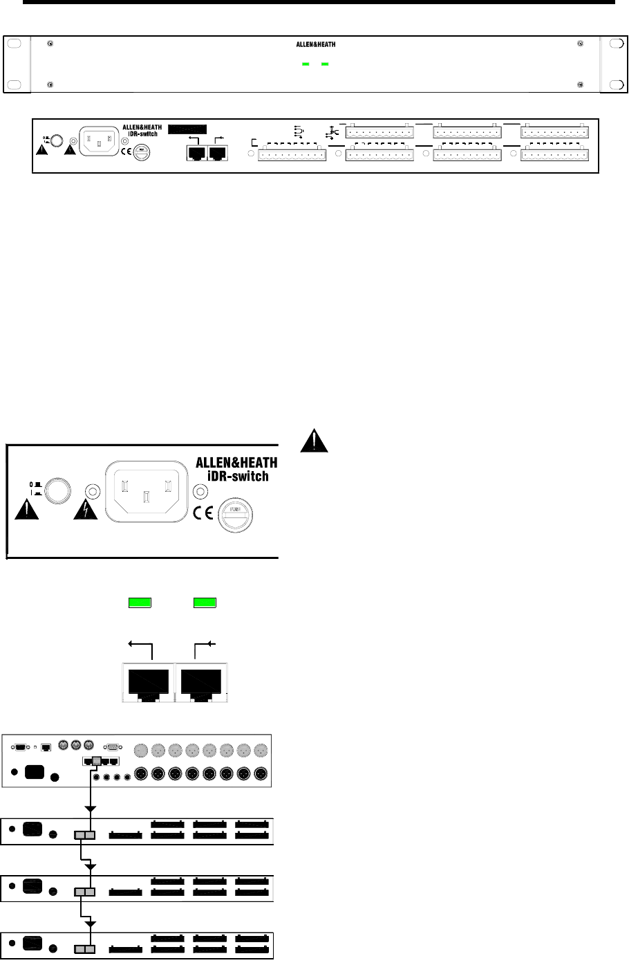
Connecting to the iDR-8 The iDR-8 communicates
with the iDR-switch using the DR-Link port. This serial
connection can be daisy chained through the 3 switch units as
shown, and then on to the iDR-in and iDR-out expanders if
fitted. Make sure you plug the DR-Link IN and OUT sockets
correctly. Use CAT5 STP cables with RJ45 connectors. Do not
use UTP cable. A standard 2 metre cable is provided with each
unit. You can use cables up to 300 metres long between units
for remote positioning. Ensure a good mains supply and solid
grounding to each unit.
Planning the system Before starting make sure you
have planned how the system is to work. Allocate the switch
inputs and logic outputs and keep a log of their intended
function. Use the iDR System Manager software to configure
the system. Simulation windows are provided for you to try out
your settings without access to the units themselves.
link power
24 IN 16 OUT SWITCH CONTROLLER
iDR-switch
VG
G 4321 G5678G 1211109 G13141516G 20191817 G21222324
SWITCH INPUTS
LOGIC OUTPUTS
123
+-
4
VGVGVG +-+-+-
567
+-
8
+-+-+-
910
+-+-+-+-
11
1214
+-+-+-
+-
1516 13
switch
G
opto
+10V
2K2
opto
+
-
V
G
+10V DC max total 500mA
open collector
+24V DC, 200mA max
+10V
FUSE: T500mAL
WARNING
THIS APPARATUS MUST BE EARTHED.
ATTENTION: REMPLACER LE FUSIBLE AVEC UN DES MEMES CARACTERISTIQUES.
FOR CONTINUED PROTECTION AGAINST RISK OF FIRE REPLACE FUSE WITH SAME TYPE AND RATING.
100 - 240V~
47-63Hz ~ 15W MAX
CAUTION: RISK OF ELECTRIC SHOCK. DO NOT OPEN.AVIS: RISQUE DE CHOC ELECTRIQUE - NE PAS OUVRIR. Made in the UK by ALLEN&HEATH LIMITED Complies with UL6500, CSA-E65, EN60065
OUT IN
DR-LINK
next previous
lin
powe
FUSE: T500mAL
WARNING
THIS APPARATUS MUST BE EARTHED.
ATTENTION: REMPLACER LE FUSIBLE AVEC UN DES MEMES CARACTERISTIQUES.
FOR CONTINUED PROTECTION AGAINST RISK OF FIRE REPLACE FUSE WITH SAME TYPE AND RATING.
100 - 240V~
47-63Hz ~ 15W MAX
CAUTION: RISK OF ELECTRIC SHOCK. DO NOT OPEN. AVIS: RISQUE DE CHOC ELECTRIQUE - NE PAS OUVRIR.
SWITCH 49-72 OUT 33-48
DR-Link
SWITCH 1-24 OUT 1-16
SWITCH 25-48 OUT 17-32
OUT IN
DR-LINK
next previous


