


44 IDR-8 User Guide
Software
Downloadable from Allen & Heath web site
iDR-8 operating code – can be updated via RS232
Uses Windows™ HyperTerminal
iDR System Manager configuration software
Uses Windows™ PC
On and off line operation
Required only for system configuration
PL Designer virtual controller design software
Uses Windows™ PC
Configured by installer
Allows restricted operator control
PL Client virtual controller
Uses Windows™ PC
For operator control from PC workstation
Clock
Time hours : minutes : seconds, 24 hour clock
Day of week
Manually enter or sync to PC
Naming
Unit name – up to 16 characters
Patch names – up to 8 characters
Input channels – up to 8 characters
Output channels – up to 8 characters
Fader group names – up to 8 characters
LCD display user text – up to 16 characters
Soft Switches
Assignable by the installer
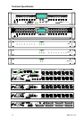
iDR-8 16x front panel
iDR-switch 24x contact closure
PL remotes various
Latching, press, release actions or unused
Level control – input, output, crosspoint, group, up,
down, up/down (using scroll keys), range limit
Mute control – on, off, toggle
Patch control – recall
Logic control – iDR-switch logic outputs, PL remotes
Soft LEDs
Assignable by the installer
iDR-8 32x front panel
iDR-in 8x front panel
iDR-out 8x front panel
iDR-switch 16x open collector outputs
PL remotes various
3-colour – green, yellow, red, off
Signal meters (3-colour), mute, static patch related
LCD Display
2x16 character, grey, backlit
Assignable display, patch related
Combinations of clock, unit name and user text
Setup menu, code update and status modes
Memory System
Up to 99 patches, memory usage dependent
Patch name – up to 8 characters, displays on PC, can
display in LCD
Select parameters to save from on screen list
Add/remove parameter edit functions
Selectable power up patch recall
Patch recall assignable to front panel and remote soft
switches
Scheduled events (clock related patch recall)
Adjustable level cross fade between patches
Parameters stored in iDR-8:
Unit name
Time and day clock
TCP/IP and PPP settings
Configured settings and patches
Parameters archived as configurations files:
Communication port preferences
Synchronisation preferences
Channel names
Fader group names
Stereo channel selection
Scheduled events
Patch contents
Power up patch (if one has been set)
Parameters stored in patches:
Fader levels and patch cross fade time
All channel processing parameters
Matrix settings
Input and output source patchbays
Input preamp settings
AMM, ducker and pager settings
Fader group settings
LCD display settings
Soft key and LED settings
iDR-switch and PL remote settings
Monitor settings
Signal generator settings
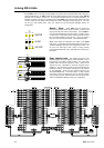
Source Patchbays
Emulates a physical patchbay
Input channel source – analog XLR 1-8, expander 9-
16, monitor LR, signal generator
Output XLR source – output channel 1-16, monitor LR
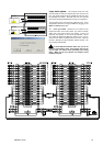
Mix Matrix
Input / output channel crosspoint matrix
Switched routing or variable level fader at each point
Fader range off to 0dB in 51 steps
48kHz mode – 16x16
96kHz mode – 8x8
Controls - set/clear individual row, column or all