


©2000 Crown International, Inc.
Circuit Theory 3-1
130447-1 Rev. A
IQ-USM 810 Service Manual
3 Circuit Theory
3.1 Overview
This section explains operation of the IQ-USM 810 cir-
cuitry. Please refer to the IQ-USM 810 Reference Manual
and IQ for Windows help files for information about the
IQ-USM 810 features and operation.
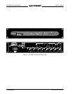
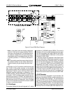
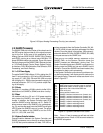
The IQ-USM 810 consists of a universal power supply
and 5 PWAs (see Figure 3.1). Each PWA has a particu-
lar function and initial troubleshooting should focus on
attempting to determine which PWA is causing the mal-
function. The PWAs are not unit-dependent, so a known
good working PWA or unit can be used to pinpoint which
PWA is faulty.
3.2 Power Supply
The universal power supply used by the IQ-USM 810
resides underneath the System Controller at the back
of the unit. It receives AC input from the IEC filter lo-
cated on the back panel and supplies +15V, –15V, and
+5VDC to the System Controller. There is a fuse located
on the supply and should be checked if the power sup-
ply is suspected. Replace fuse with the same rated
type only.
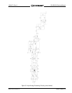
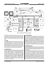
3.3 Input
The input Printed Wire Assembly (PWA) is located at
the back of the unit on the bottom. It offers eight bal-
anced input audio channels via 3 pin connectors. Fig-
ure 3.2 shows the block diagram of the input PWA. The
PWA is composed of the following sections: Input Ana-
log Processing, Clock Signals, A/D Conversion, and DC
Voltages.
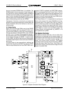
3.3.1 Input Analog Processing
Each input channel has analog processing that pro-
vides filtering, line/mic switching, phantom power, op-
tional input transformer isolation, and variable gain con-
trol. The balanced output of each analog channel is fed
to a shared A/D converter.
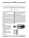
All eight analog input channels are identical (Figure 3.3).
The balanced analog input is RF filtered by FB100,
FB101, C102, and C103. Capacitors C100 and C101
provide filtering to ensure that no noise from the unit
goes out. R100-102 provide a 10 k ohm balanced input
impedance in the line mode. Switch SW100 provides
switching between Phantom, Line, and Mic modes.
• Phantom: SW100 shorts R103/C104 and R104/
C105 to allow the phantom DC voltage (+24VDC)
to be available on the input connector. In addi-
tion, no gain reduction is provided on the input
path. R105 & R106 allows current limiting of the
phantom voltage.
Figure 3.1 Overall Block Diagram