


©2000 Crown International, Inc.
Maintenance 4-9
130447-1 Rev. A
IQ-USM 810 Service Manual
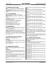
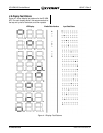
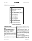
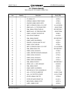
4.10 Error Codes
Figure 4.2 IQ-USM 810 Error Codes
E01 UART failed system controller power-on self test
E02 RAM failed system controller power-on self test
E03 Application code in flash failed crc test
E04 Flash verify error
E05 Unrecoverable firmware error
E10 Sharc 0 interface hardware error (timeout, etc.)
E11 Sharc 1 interface hardware error (timeout, etc.)
E12 Sharc 2 interface hardware error (timeout, etc.)
E13 Sharc 3 interface hardware error (timeout, etc.)
E14 Sharc 0 failed SRAM test
E15 Sharc 1 failed SRAM test
E16 Sharc 2 failed SRAM test
E17 Sharc 3 failed SRAM test
E18 Sharc 0 failed SDRAM test
E19 Sharc 1 failed SDRAM test
E20 Sharc 2 failed SDRAM test
E21 Sharc 3 failed SDRAM test
E22 Sharc 0 software watchdog timeout
E23 Sharc 1 software watchdog timeout
E24 Sharc 2 software watchdog timeout
E25 Sharc 3 software watchdog timeout
Figure 4.2 shows error codes for the IQ-USM 810.
4.11 Troubleshooting FAQs
The following FAQs are provided to answer a few ques-
tions that may arise in the course of servicing the IQ-
USM 810.
Q. What does the display indicate during power up?
A. When the IQ-USM 810 initially powers up, it
displays the following:
dSP…810…SH0…SH1…SH2…SH3…Pxx.
This is the boot sequence for the internal processors.
Initially, the System Controller processor boots, then it
sequentially boots the four DSP processors (SH0-3).
After the System Controller processor successfully boots
all four DSP processors, audio processing is allowed to
begin.
Q. When I power up the IQ-USM 810, it continues to boot.
What's up?
A. If the System Controller processor encounters an error
during the boot process, it terminates the process at
that point, displays an error code on the front panel,
then reboots. See Section 4.10 for a list of error codes.
Q. What is the most common error?
A. Hopefully, no error is common. When “E22” is dis-
played as the error code, it is most likely due to a loss of
digital audio clocking from the Input board. The short
26-pin ribbon cable carries digital audio and clocking
from the Input board to the SHARC board. Check for
creation of Master Clock (12.288 MHz), Serial Clock
(3.032 MHz), and Frame Clock (48 kHz) by the Input
board.
Q. How do I reboot the IQ-USM 810?
A. There are a couple of different ways to reboot the IQ-
USM 810. The most straightforward way is to remove
the AC power cord from the IEC320 connector on the
rear panel, then replace the cord. The loss of AC power