


©2000 Crown International, Inc.
IQ-USM 810 Service Manual
3-2 Circuit Theory
130447-1 Rev. A
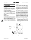
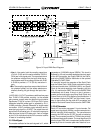
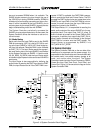
• Line: In Line mode, both the coupling capacitors
(C104 & C105) and the series resistors (R103 &
R104) are in the signal path. The capacitors block
the phantom voltage from the input while the se-
ries resistors work as a voltage divider with R105
& R106 to provide a 17.7x (25 db) reduction in
gain.
• Mic: The coupling capacitors are provided to block
the phantom power, but the series resistors are
shorted, allowing full gain through the input chan-
nel.
L100/C106 (L101/C107) provide an additional low-pass
filter. C108 & C109 provide coupling to the variable
gain preamp, except when the optional input isolation
transformer (T100) is in place. Q100 and Q101 form a
differential amplifier whose gain is adjusted by R111.
U100B provides a filtered differential to single-ended
conversion. U101C provides a gain reduction and bi-
ases the input signal to +2.2VDC. The output bias volt-
age of the A/D converter's pin 15 is fed to the op amp to
bias the signal to the A/D's bias point. Lack of voltage
at pin15 is an indication that the A/D converter is either
in reset or is not being clocked.
3.3.2 Clock Signals
The master oscillator for the audio signals is Y1, which
generates a 12.288 MHz signal (256Fs). This clock is
buffered by U3 and provides separate outputs to each
of the A/D converters, the Output PWA for the DAC's,
and to the SHARC PWA for distribution to the optional
CobraNet™ (CNET) PWA.
U1 normally acts as the generator of the Serial Clock
and the Frame Clock. Serial Clock provides the timing
of the serial audio data, 3.032 MHz (64Fs), and Frame
Clock is the actual sampling clock frequency, 48 kHz
(Fs). U1 monitors the CNET line from the SHARC PWA
immediately out of reset. If the pin is low, it acts as a
master source and begins providing Serial Clock and
Frame Clock to U4 & U5 for buffering and distribution. If
U1 senses a high on the CNET pin out of reset, it oper-
ates in slave mode like the other A/D converters and
waits for Serial and Frame Clocks from the CNET PWA.
3.3.3 A/D Conversion
Each A/D converter processes 2 input channels. Full
scale input signals are 2.82Vp-p and are sampled at a
48-kHz rate with 24-bit resolution. The converters are
reset by the DSP's by the IO_RST line with a low being
reset. The converters provide an I
2
S 32-bit time-division
multiplexed data audio stream. The most significant 24
bits are linear PCM (two's complement) audio data fol-
lowed by 8 bits of converter peak hold data that is un-
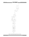
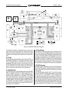
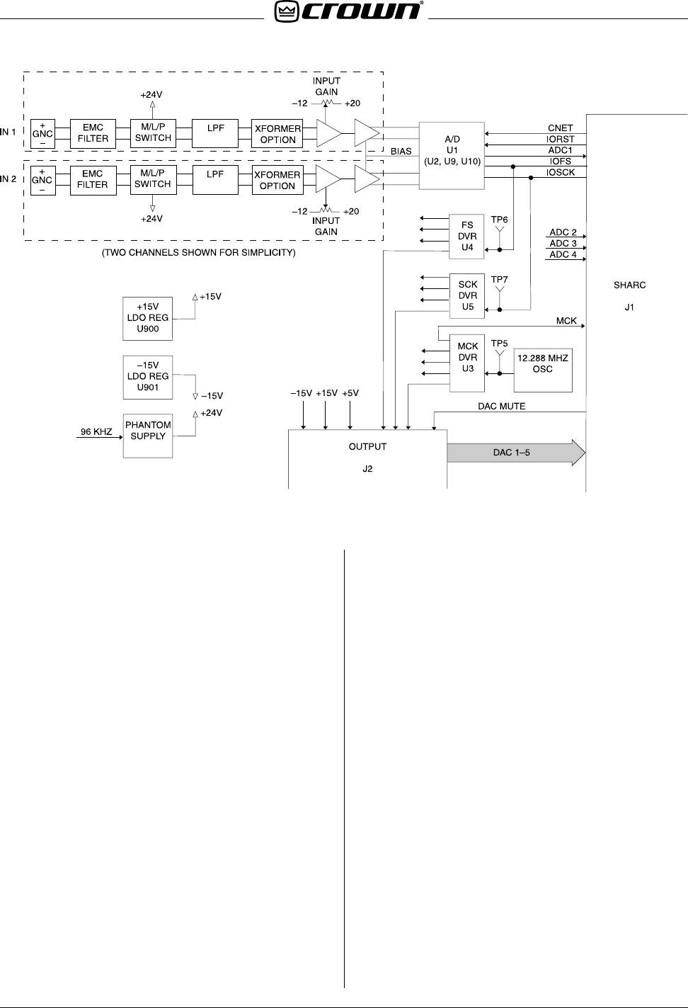
Figure 3.2 Input PWA Block Diagram