


©2000 Crown International, Inc.
Circuit Theory 3-5
130447-1 Rev. A
IQ-USM 810 Service Manual
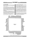
3.5 SHARC Processing
The SHARC PWA sits in the center of the chassis and is
the DSP engine that provides all of the signal process-
ing for the unit. At the core of this processing is four
Analog Devices ADSP-21065L SHARC 32-bit floating
point DSP's running at an internal rate of 60 MHz. Full
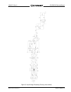
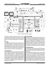
speed SDRAM interface is provided. Figure 3.8 shows
the block diagram of the SHARC PWA. Features include
a +3.3V Power Supply, Clocks, Reset, System Control-
ler Interface, PLD's, Bus Arbitration, Bus Utilization, DSP
Processing, and Audio Routing.
3.5.1 +3.3V Power Supply
The entire SHARC PWA utilizes +3.3V by taking the +5V
from P1 and converts it to +3.3V using a 300-kHz switch-
ing supply IC, U29. Q2 & Q3 work with U29 to control
the charging of L1. R200 current senses the supply for
overload protection. C27 & C113 provide output filter-
ing of the supply.
3.5.2 Clocks
Oscillator Y1 provides a 30-MHz clock to buffer U3 for
distribution to all SHARC's, SRAM, and other circuitry.
3.5.3 Reset
U8 monitors both the +5V and +3.3V power supplies
and places the SHARC's into reset if either supply
droops. In addition, the System Controller uses U8 to
reset the SHARC's using pulldown via D1. Switch S1
allows manual reset of the SHARC's for troubleshoot-
ing. Q1 monitors the reset line to the SHARC's and lights
LED E5 when the SHARC's are not in reset. The active
low \RST line resets all four SHARC's and the PLD's
(U9, U11, U23, U24, and U30).
3.5.4 System Controller Interface
Communications between the System Controller and
SHARC processors occurs through a series of latches
(U12-22) that provide address and data. PLD U23 re-
ceives commands from the System Controller (SH_A0-
2, \HCS, HR/W) to load data and addresses into these
latches. Once the data is in the latches, U23 communi-
cates with Arbiter PLD U24 (\SYSBR, \SYSBG, \RD, \WR)
to request access to the SHARC bus.
There are no non-volatile memory resources on the
SHARC PWA, so the System Controller stores the
SHARC firmware and downloads it during boot. The
System Controller boots each SHARC in succession by
loading code into SRAM and into each SHARC via the
Interface. Once all four SHARC have been booted, they
are allowed to begin audio processing.
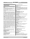
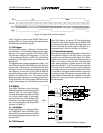
If the System Controller encounters any problems dur-
ing the boot process, it will display an error code on the
front panel display. These error codes are shown in the
table in Figure 3.7:
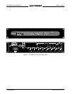
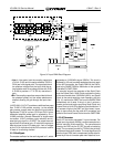
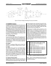
Figure 3.6 Output Analog Processing Circuitry (one channel)
Note: Errors 1-9 are for power-up self test and other
miscellaneous errors. Errors 10-25 are errors related to
the SHARC subsystem.
Figure 3.7 System Controller Error Codes
E1 UART failed system controller power-on self test
E2 RAM failed system controller power-on self test
E3 Application code in flash failed CRC test
E4 Flash verify error
E5 Unrecoverable firmware error
E10 SHARC 0 interface hardware error (timeout, etc.)
E11 SHARC 1 interface hardware error (timeout, etc.)
E12 SHARC 2 interface hardware error (timeout, etc.)
E13 SHARC 3 interface hardware error (timeout, etc.)
E22 SHARC 0 software watchdog timeout
E23 SHARC 1 software watchdog timeout
E24 SHARC 2 software watchdog timeout
E25 SHARC 3 software watchdog timeout