13
Getting Started Connections Basic Operations Specifi cations Troubleshooting
Effector Function Fader Start UtilityUSB
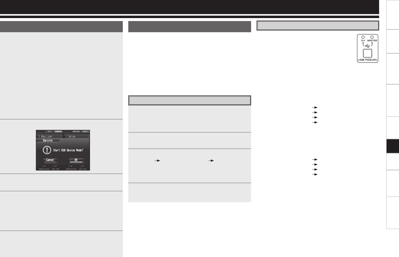
Setting the USB audio input
One of the two modes below is set using the USB
ASSIGN CH/MASTER
button for the USB audio input
assignment destinations.
The LED on the side corresponding to the mode
selected lights.
The USB audio input levels can be adjusted using
Utility settings. The adjustment values are stored on a
mode by mode basis.
q CH INPUT mode
Select this mode when mixing sound using only the DN-X1700
without using the mixer functions of the DJ software.
The USB audio input signals are assigned using the confi guration
shown below.
USB channel 1 and 2 inputs
Input channel 1
USB channel 3 and 4 inputs
Input channel 2
USB channel 5 and 6 inputs Input channel 3
USB channel 7 and 8 inputs Input channel 4
w MASTER mode
Select this mode when using both the mixer functions of the DJ
software and the DN-X1700’s functions.
The USB audio input signals are assigned to the buses shown
below.
USB channel 1 and 2 inputs Master bus
USB channel 3 and 4 inputs Cue monitor bus
USB channel 5 and 6 inputs
Disabled
USB channel 7 and 8 inputs
Disabled
The mixer output of the DJ software is mixed in the buses using
the DN-X1700.
* Ensure that the audio output settings of the DJ software correspond
to the specifi cations given above.
USB audio
This unit features a 24-bit 96 kHz USB audio input/output sound card
function which supports up to 8 channels (4 stereo systems). The
sampling frequency can be set to 44.1 kHz, 48 kHz or 96 kHz using a
Utility setting (factory setting: 96 kHz).
* When the unit is connected to a computer which runs Windows XP,
Vista or a similar operating system, install DENON DJ ASIO driver
Ver2 contained on the CD-ROM provided. If the Ver1 driver is already
installed, fi rst uninstall it, and then install the Ver2 driver.
* Depending on the computer used, select the PC/MAC section
settings under System Setting among the Utility settings.
Selecting the USB mode
The respective functions given below are carried out in the operation
modes of the USB A terminal (USB host mode) and USB B terminal
(USB device mode).
USB A :
•
Preset data import/export function
•
Version upgrading
USB B :
•
USB audio interface function
•
USB MIDI interface function
The operation mode to be established when the unit's
power is turned on can be selected by a Utility setting.
(Factory setting: USB A)
To switch from USB A (host mode) to USB B (device mode):
1
Press the UTILITY/–USB A/USB B button for one
second.
2
Operation now transfers to the screen shown below.
3
Select OK/Cancel using the EFX SELECT control
(EFX2), and press the button to enter the selection.
4
The indicator changes from USB-A to USB-B, and the
device mode is established.
(* When a speci c period of time elapses with no
computer connected to the USB B terminal, the
indicator changes back to USB-A, and the host mode
is automatically selected.)
5
To select the host mode again, press the UTILITY/–USB
A/USB B button for one second, and select the settings
by following the same steps.
USB Settings
Setting the USB audio output
Any sound source of the 4 systems provided—1 to 4 input channels
(Pre EQ), mic input (Post Send VR), master output (Pre Limiter) or
REC output—can be selected as the USB audio output.
The USB audio output level can be adjusted using a Utility setting.
1
Press the UTILITY/–USB A/USB B button. The Utility
setting screen is displayed.
2
Using the EFX SELECT control (EFX2), select Audio
Setting USB Audio Setting Output Source
Select. One of the audio sources assigned to the USB
output channels is selected on the selection screen
displayed.
3
Press the UTILITY/–USB A/USB B button. The Utility
setting screen is closed.
USB


