


– 10 – ETAsys.com
Specifications are subject to change without notice.
1601 Jack McKay Blvd. • Ennis, Texas 75119 U.S.A.
Telephone: 800-321-6699 • Fax: 800-996-3821
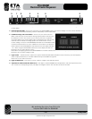
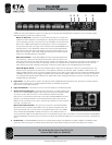
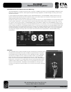
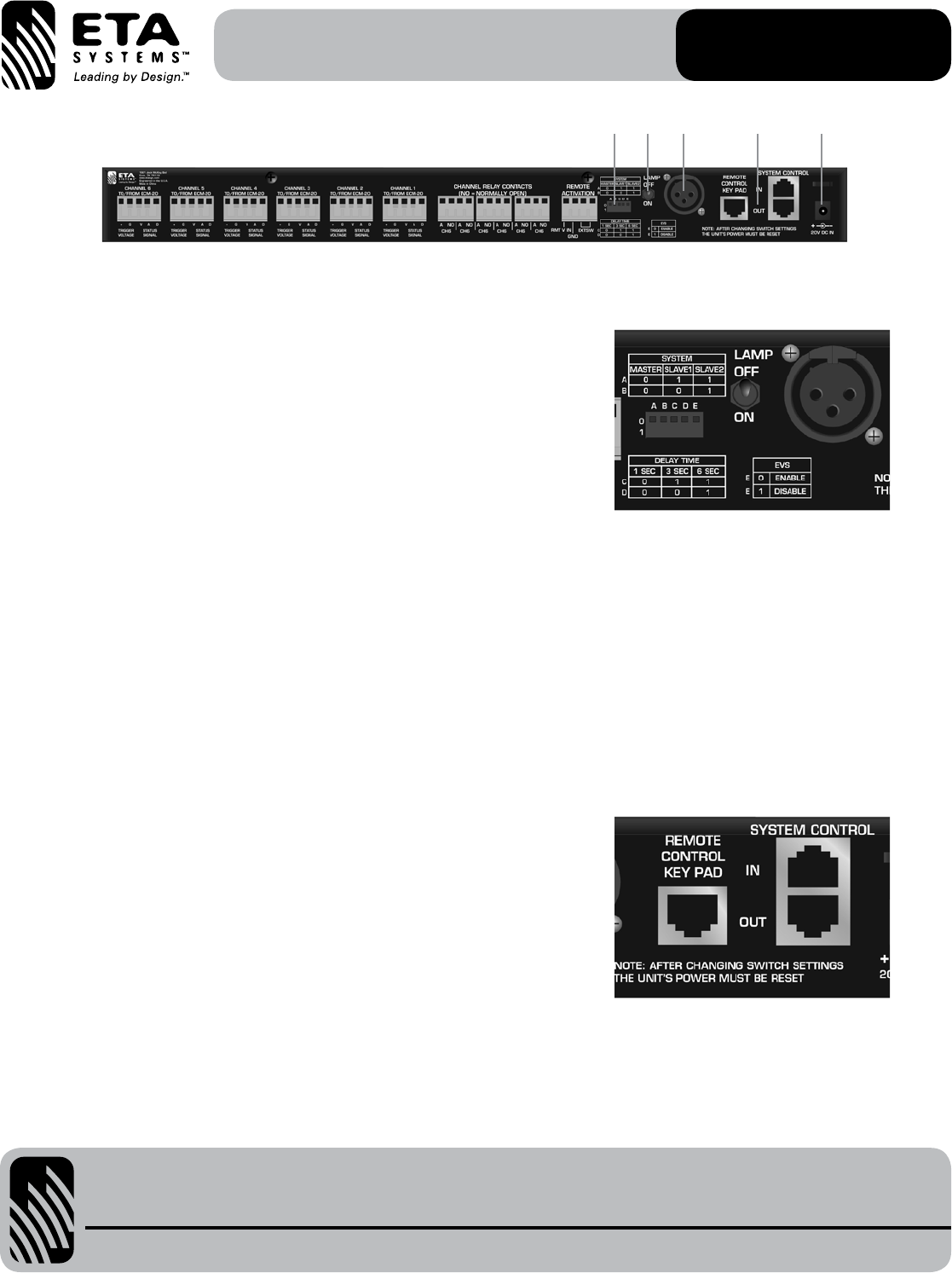
4. Trigger Switches – Up to three ETA-ECS6RM units can be daisy chained together giving you 18 sequenced outputs. To do so you
need to set the timing sequence of each unit. There are four dip switches that determine the position of the unit and the delay
between sequencing. Follow the steps for setup.
Master or Slave Unit – Determine if you are daisy chaining two or three units
together. Choose the position of the sequence in perspective to the equipment
you are activating. The first unit will be known as the Master Unit, all others are
Slave Units. A & B switches determine the position of the unit and sequence
timing. Follow the chart to the right and on the back of the ETA-ECS6RM for the
settings. When a unit is selected as a Slave Unit the Front Panel Slave Mode
LED will illuminate. Also follow the System Control Port section below for unit
daisy chain connection. Note: After changing a setting the unit power must be
reset for the changed settings to take effect.
Delay Time Switches – The ETA-ECS6RM has three timing settings between
each sequence, 1 Second, 3 Seconds and 6 Seconds. Follow the chart for the
settings for Switches C & D. When daisy chaining multiple units together each unit’s settings only relate to that individual unit.
For example, you can set Unit One for 3 Seconds, Unit Two for 1 Second and Unit Three for 6 Seconds or all can have the
same setting. Note: After changing a setting the unit power must be reset for the changed settings to take effect.
Auto EVS Bypass Switch – The Extreme Voltage Shutdown (EVS) has two settings to meet your install requirements. The
selection of the settings are via switches E or F. The selection affects all six channels. When “Enabled” the EVS circuit will
trigger an ECM shutdown when an extreme voltage condition occurs and will auto reset when the voltage has stabilized. When
“Disabled” the EVS circuitry will trigger a shutdown during and extreme voltage condition and will not turn back on unless the
unit is sequenced. See EVS feature definition for details. Note: After changing a setting the unit power must be reset for the
changed setting to take effect.
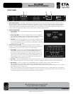
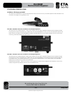
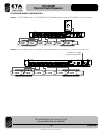
5 Light Socket – The XLR socket is used for the optional 12VDC AP-GNL18 LED Gooseneck Lamp. One lamp, from ETA Systems
sister company Atlas Power, is included. Additional lamps are available through ETA.
Note: This is not an audio connection.
6 Light On/Off Switch – This switch turns On or Off the voltage to the XLR lamp socket.
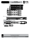
7 System Control In/Out Ports – These ports are used when you need to daisy chain
more than one ETA-ECS6RM together. Up to three units can be connected in series.
Connection is via a RJ45 connector. A common Ethernet cable can be used.
Note: This is not an IP Ethernet port and is only used for ETA-ECS6RM connectivity
between units. Distance between units can be several feet apart. Start with the
Master Unit by connecting to the “OUT” connector port and then into the first Slave
units “IN” connector port.
Remote Control Key Pad Port – This port is for connection with the ECS-KSW6
Remote Key Switch / System Status Plate. This is an optional accessory item that
allows you activate, lock out and monitor the AC Mains system from up to 1000ft
away. See Remote ECS-KSW6 for details. Connection is via a RJ45 connector. A
common Ethernet cable can be used. Note: This is not an IP Ethernet port and is only used for connectivity between ETA-ECS6RM
and the ECS-KSW6 units. Wiring of this connector is the same as an Ethernet cable. Do not mis wire the connector or damage may
occur.
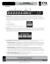
8 DC Power IN – The ETA-ECS6RM comes with a universal power supply that operates from 100V – 240VAC. The 24VDC output
connects to the DC input jack. A cable tie can be used with the slot above the DC jack to secure the cable to the chassis.
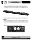
ETA-ECS6RM
Electrical Control Sequencer
4 76 5 8