


– 7 – ETAsys.com
Specifications are subject to change without notice.
1601 Jack McKay Blvd. • Ennis, Texas 75119 U.S.A.
Telephone: 800-321-6699 • Fax: 800-996-3821
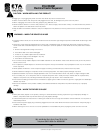
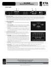
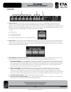
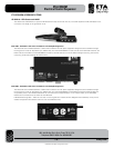
FRONT PANEL
1. System Activation Switch – To activate or deactivate the system sequence, press the momentary switch once. There must be at
least one ECM (Electrical Control Module) connected for a sequence to occur. If there are no Channel Status LEDs illuminated or
voltage reading, no sequence will occur. The unit will only sequence through the number of ECM modules connected. Note: If
there are ECM modules connected and the Channel Status LED are illuminated but the Activation Switch has no effect, the unit
may be in External Trigger Mode. Refer to Channel Status LEDs and Relay Contacts sections.
2. Unit Activation Mode LEDs
• SystemONLED – When the ETA-ECS6RM is activated the System ON LED
will illuminate.
• ExteriorTriggerMode – If an External Trigger Voltage or Switch is applied to
activate the ETA-ECS6RM the Exterior Trigger Mode LED will be illuminated.
Note: When LED is ON the System Activation switch is defeated.
• SlaveMode – When the Slave Mode LED is Illuminated it indicates that there
are more than one ETA-ECS6RM connected to the trigger sequencing. Up
to three ETA-ECS6RM units can be connected in series. Refer to Rear Panel
System Control for more details.
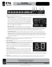
3. Channel Activation Status LEDs – There are six Bi-Color LEDs that represent
Channels 1 thru 6 of the ETA-ECS6RM. These LEDs indicate when there is AC
voltage present or if there is an error within the AC Mains System.
• Red“Standby” – If a Channel on an ETA-ECM20, ETA-ECM20M, ETA-15SH,
or ETA-20SH module is connected to the ETA-ECS6RM a Red LED will
illuminate indicating that Channel is active and in Standby mode. If there
are Channels of the ETA-ECS6RM with no ECM modules connected, NO
LED for that Channel will illuminate indicating NO CONNECTION (nC) has
been established. Note: If the Channel is selected for monitoring has no
CONNECTION the LCD display will read “nC”.
• Green“ON” – When the ETA-ECS6RM has been activated and sequencing is completed, the LED for channels that have an
ECM module connected will turn from Red “Standby” to Green to indicate the ECM module is activated and operational.
• Red“Flashing” – If a fault in voltage occurs the ECM-6RM will shut the ECM module off and will report back to the
ETA-ECS6RM causing the Channel Activation LED to flash Red, indicating an error has occurred.
Note: The LED will continue to flash until the voltage has stabilized at the ECM module and ETA-ECS6RM is reset. To reset the
ETA-ECS6RM, restart the sequencing.
Note: It is also possible to have Channels flashing Red while others are operational with a steady Green LED. This is because
an ETA-15SH or ETA-20SH can be placed on a different AC leg up to 1000' away. Not all ECM modules may see the same error
in AC Mains voltage thus allowing some ECM modules to remain operational.
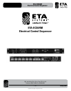
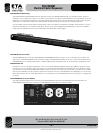
ETA-ECS6RM
Electrical Control Sequencer
1
23