


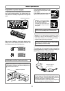
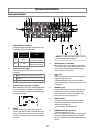
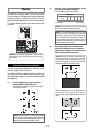
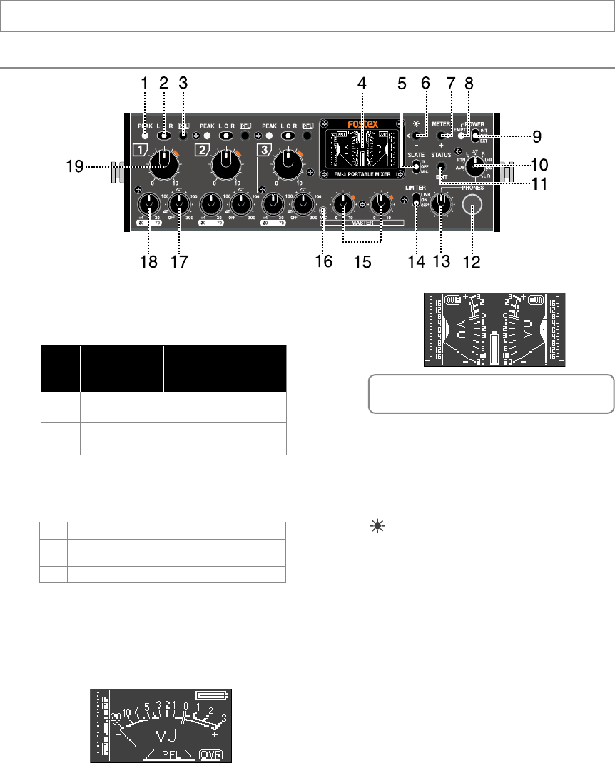
1. PEAK indicators (1 through 3)
Each indicator lights according to the signal level of the
corresponding input channel as follows.
Front panel section
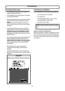
4. Display
The 128 x 64 dot-matrix display using organic EL
devices shows the VU (needle) and peak (bar-graph)
meters,batterystatus,etc.Whenyourstturnonthe
unit after purchasing, the stereo VU and peak meters
are shown.
5. [SLATE] switch (1k / OFF / MIC)
When it is set to “1k”, a 1-kHz slate tone is generated
and sent to the stereo L and R busses. While you hold it
down to “MIC”, the internal slate microphone signal is
sent to the stereo L and R busses.
6. [ ] / [-] key
Holding down this key for a second or more enters the
brightness adjustment mode.
In the brightness adjustment mode, meter selection
mode or status display mode, this key acts as the [-] key
(see page 14).
7. [METER] / [+] key
Holding down this key for a second or more enters the
meter selection mode. In the brightness adjustment
mode, meter selection mode or status display mode,
this key acts as the [+] key (see page 15).
8. EMPTY indicator
Thisindicatorasheswhenthebatteryvoltagefalls
below the threshold while you operate the unit on
battery power (see page 20).
In normal condition, this indicator is unlit.
9. [POWER] switch (INT / OFF / EXT)
This switch turns the unit on or off.
When you operate the unit on external power (using the
optional AC adaptor or external battery), set it to EXT.
When you operate the unit on internal battery power, set
it to INT.
3. [PFL] (Pre Fader Listen) keys (1 through 3)
While pressing down the key, the pre-fader signal (before
the input channel fader) is output from the [PHONES]
jacks. In this condition, the display shows the PFL signal
level metering as below.
2. Pan switches (1 through 3)
Each switch set the pan position of the corresponding
input sig
nal.
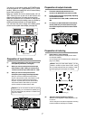
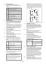
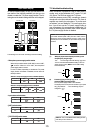
Color
Green
Red
Lighting level
(compared with the
reference level)
Details
+8dB
+17dB
Approximately -12dB below
the internal maximum level
Approximately -3dB below
the internal maximum level
L
C
The signal is assigned to the left channel of the stereo buss.
The signal is assigned to both the left and right channels of the
stereo buss.
R
The signal is assigned to the right channel of the stereo buss.
<Memo>:
For details about the contents of the dis-
play, see “Display details” on page 14.
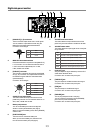
Names and functions
10