


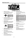
11. [STATUS] / [EDIT] key
Holding down this key for a second or more enters the
status mode. In this mode, you can switch among status
display pages as well as you can edit parameters (see
page 15).
In the brightness adjustment mode, meter selection mode
or status display mode, this key acts as the [EDIT] key (see
page15).Pressingthiskeybrieyexitsthecurrentmode
while pressing this key for a second or more enters or
exits the parameter editing mode.
12. 1/4-inch [PHONES] jack
You can connect stereo headphones with the 1/4-inch
plug for monitoring.
13. Headphones level control
This control is used to adjust the output level of both the
1/4-inch and mini [PHONES] jacks.
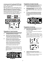
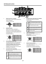
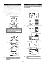
14. [LIMITER] switch (ON, OFF, LINK)
This switch enables or disables the limiter function.
The limiter can work individually or in link, as described
below.
The limiter circuit is inserted after the MASTER fader.
15. [MASTER] faders (L and R)
These faders control stereo left and right buss output
levels. The scale position in orange shows the reference
position. These faders are push-locked type. Pressing a
fader puts it to the up position. Pressing it again puts it to
thedownposition(atposition).
16. [MIC]
A slate microphone is built in. While holding down the
[SLATE] switch to the “MIC” position, the slate
microphone is active and the signal from the microphone
is sent to the stereo buss.
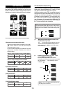
17. HPF controls (1 through 3)
Eachcontrolsetsthehighpasslterfunction.
These controls are push-locked type. Pressing a control
puts it to the up position. Pressing it again puts it to the
downposition(atposition).
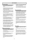
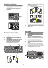
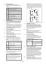
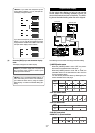
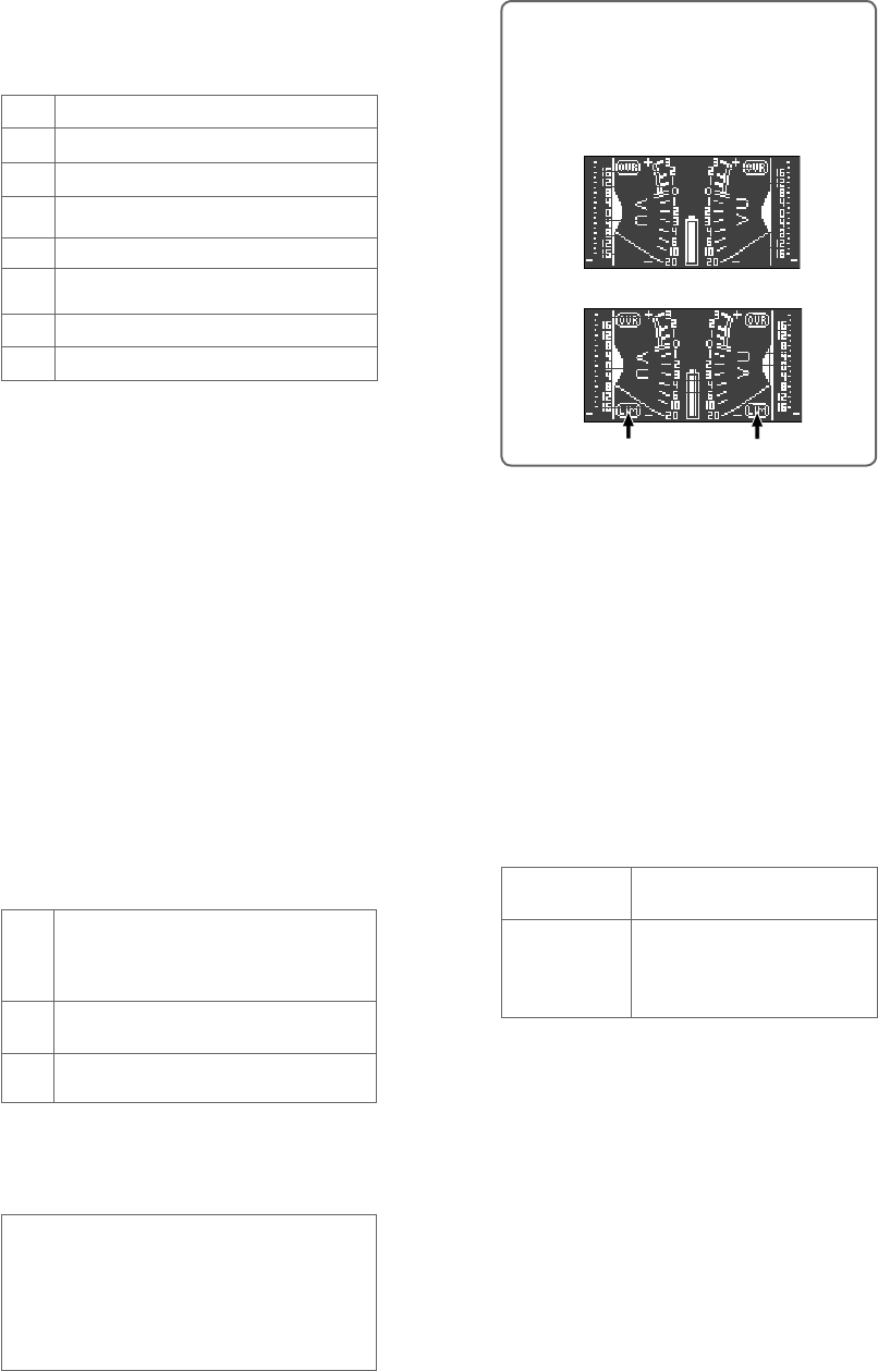
<Memo>:
When you select the [LIMITER] switch to
ON or LINK, the meter display shows “LIM” (pointed
by arrows below). When the limiter is working, “LIM”
ashes.Thefollowingshowsdisplayexamplesofthe
stereo meter display.
<Factory preset values>
•Attacktime:Approximately5milliseconds(xed)
•Releasetime:Approximately200milliseconds(xed)
• Threshold: +12 dB (can be changed to +6 dB)
• Ratio: 5:1 (can be changed to 3:1)
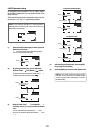
RTN
L
ST
Signals input to the [RTN] connector.
A signal output from the [MAIN OUT L] connector in mono.
Signals output from the [MAIN OUT L and R] connectors in
stereo.
R
L+R
A signal output from the [MAIN OUT R] connector in mono.
Signals output from the [MAIN OUT L and R] connectors
in mono (L component of MS).
MS
MS decoded signals are output.
AUX
Signals input to the [AUX IN] connector.
L-R
R component of MS is output in mono.
ON
OFF
The limiter function is enabled. Each of the left and right
limiters works independently.
The limiter function is disabled (the limiter circuit is by-
passed).
LINK
The limiter function is enabled with the left and right
channels linked. If either of left and right channel signals
exceeds the threshold, both the left and right channel
limiters work in the same way.
The limiter parameters are factory-preset as shown be-
low.
You can change the threshold level and ratio from the
output status display (see page 18).
When the switch is set to OFF
When the switch is set to ON or LINK
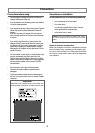
10. Monitor select switch
This switch selects the signal monitored by the
headphones connected to the [PHONE] jacks (1/4-inch
and mini).
“LIM” icon
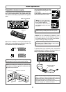
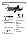
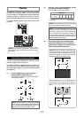
18. Input trim controls (1 through 3)
Each control adjusts the input gain of the corresponding
input channel. When the input select switch is set to MIC,
you can adjust the gain between -70 dBu and -30 dBu.
When the input select switch is set to LINE, you can
adjust the gain between -20 dBu and +4 dBu.
It is recommend to adjust the control so that the PEAK
indicator does not light in red at the maximum input level.
These controls are push-locked type. Pressing a control
puts it to the up position. Pressing it again puts it to the
downposition(atposition).
19. Channel faders (1 through 3)
Each fader controls the signal level sent to the stereo buss.
The scale position in orange shows the reference position.
ON
By turning the control right from the Off
position, it clicks and the HPF circuit gets
active. Depending on the position, the roll-
off frequency changes between 40 Hz and
300 Hz (-12 dB/oct).
OFF
(leftmost position)
The HPF circuit is bypassed.
11
“LIM” icon