


6
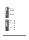
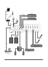
Pin connections on Connectors
XLR (input, output): pin1=Ground, pin2= hot(s+), pin3=cold(s-)
Cinch: tip= Signal (left or right), Ring= Ground
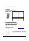
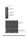
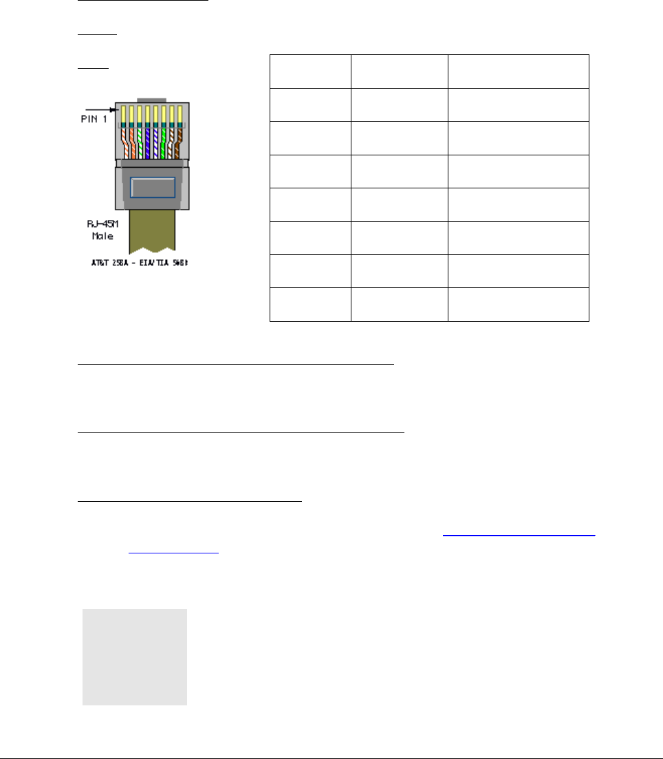
RJ45 (RS485) Wall panel:
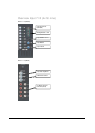
Speakon (Left, Amplified Outputs Zone 1 and 2):
pin1+ = left out, pin1- = gnd, pin2+ = right out, pin2- = gnd
Speakon (Right, Amplified Outputs Zone 1 and 2):
pin1+ = right out, pin1- = gnd, pin2+ = /, pin2- = /
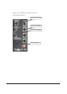
RS232 (serial connection interface)
The serial data protocol and wiring can be downloaded at www.audac.be/download or can be
asked at info@audac.be.
ATTENTION
The Cat5 cabling must always be ‘straight’. In case of self made
cabling, it must be done as described above, to make the system
work properly.
Pin 1 White-Orange
/
Pin 2 Orange /
Pin 3 White-Green +12V DC
Pin 4 Blue RS485 A
Pin 5 White-Blue RS485 B
Pin 6 Green GND
Pin 7 White-Brown /
Pin 8 Brown /
$