


9
ATTAX-MANUAL
ENGLISH
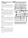
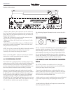
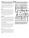
To connect a signal processor:
- Connect the device's INPUT to the ATTAX SEND jack and
its OUTPUT to the ATTAX RETURN jack.
- Activate the FX LOOP via the included STAGEBOARD's
FX footswitch.
- Adjust the FX loop's level to the signal processor's level.
Press the -10 dB switch for effects devices that are designed
for guitar signals. If the switch is not pushed in, the signal
level remains at line level for 19" rack-mounted processors.
NOTE: It is usually more difficult to determine levels for
multi-effects processors featuring integrated "preamps."
These do not allow direct access to the FX section, so the
signal actually runs through two preamps. Effects processors
without these "preamp" sections are more suitable for use in
FX loops because the sound quality and dynamics are sub-
stantially better. However, if you own one of these compact
devices, dial in the FX unit's most dynamic and cleanest
sound. If you want to use any of the FX unit's "preamp" sec-
tion sounds, we recommend you use a separate
switcher/looper to switch back and forth between the two
preamps. You can eliminate the ATTAX 100 preamp from
the signal chain by using the return side only to route the
FX processor's output signal to the ATTAX.
- Adjust the relationship between the original signal and
processed signal via the FX MIX pot located on the front
panel (towards DRY = more original signal, towards WET =
more processed signal).
NOTE: Some signal processors cause phase cancellations
that are detrimental to the overall sound. In this case, turn
the FX control all the way to the right (WET). The effects
loop then operates as a conventional serial loop, i.e. the
volume relationship between the original and the processed
signal must be adjusted at the processor. The same holds
true if you want 100% of the signal to be processed (for
instance for extreme delays and volume pedals in the FX
loop).
TIP: If you choose not to connect a signal processor/effects
device to the FX loop, you could connect a second instru-
ment or a tape deck. For instance you could connect ano-
ther guitar, keyboards, drum machine, tape player, etc. for
rehearsals or practice sessions. When you use the FX return
as a second input channel, the FX-MIX knob is used to
balance the respective volumes of your guitar and the other
connected signal source. Another option is open to you if
you do not connect a signal processor: use the loop as an
alternate MASTER volume preset. Proceed as follows:
- Activate the FX loop.
- Dial in a separate MASTER VOLUME setting via the FX
MIX pot (to the left towards DRY = volume up, to the right
towards WET = volume down).
- You can switch back and forth between the two MASTER
VOLUMES via the FX footswitch. If the MIDI option is
installed, you can also activate the alternate MASTER
VOLUME via a MIDI command.
4.3 THE ATTAX 100 AND MIDI
Once the MSM-1 MIDI Module has been installed, you can
execute the majority of ATTAX 100 switching operations via
MIDI. Simultaneous switching of both the ATTAX 100 and
the multi-effects processor is certainly the most convenient
handling option.
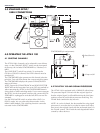
Installation of the MSM-1 MIDI Module:
NOTE: The MSM-1 Module must be installed by a qualified
service technician. The following instructions are for service
personnel only.
- Unplug the amp's mains cord and speaker cables.
- Remove the cover plate from the MIDI Module port on the
chassis' rear panel.
- Remove the amp chassis from the wood cabinet. For the
combo version, after unplugging the speaker cable, remove
the four retainer screws at the top of the amp. For the head
version, remove the front panel cover to access the chassis
retainer screws. Make sure that you do not damage the
reverb cable when you pull the chassis out.
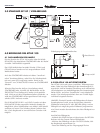
- Insert the included MSM-1 ribbon cable connector plug in
the MSM 1's socket so that the color-coded wire faces the
notch on the socket. Note that the two flat cable connector
plugs face away from the module in different directions.
Select the plug that allows for the shortest signal path. Take
care you do not bend the contact points when inserting the
plug.
MSM-1 socket and indicator notch.
- Insert the MSM-1 in the module chamber and fasten it to
the chassis using the four screws that you removed from the
cover plate. Ensure the electronic components and the
module inscriptions on the rear panel are facing right-side
up.