


21
30
20
OO
40
50
60
30
20
OO
40
50
60
dB
10
5
5
U
10
dB
10
5
5
U
10
U
OO
+10
U
U
OO
+20
O
O
+20
28
10
7
4
2
0
2
4
7
10
20
30
LEVEL
SET
LEFT RIGHT
MAIN MIX
SOLO
MODE
LEVEL SET (PFL)
NORMAL (AFL)
C-R/SOURCE
POWER
PHANTOM
RUDE
SOLO
LIGHT
AUX 1
SELECT
EFX TO
MONITOR
AUX 1 MASTER
AUX
RETURN
1
2
PRE
POST
MAIN MIXCTL ROOM /SUBMIX
NORMALLED
0dB=0dBu
ALT 3
–
4
TAPE
ASSIGN
TO MAIN MIX
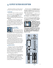
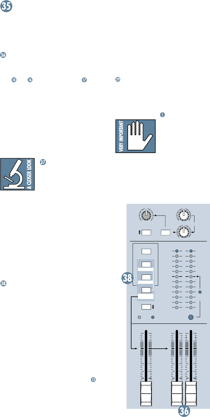
Still with us? Good for you. Here come the
tricky parts, where the mixing is really done.
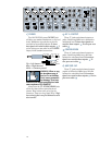
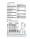
MAIN MIX
As the name implies, this fader controls the
levels of signals sent to the
MAIN OUTPUTS
:
XLR
,
1
⁄
4
" and RCA
TAPE OUT
. All
channels and
AUX RETURNS
that are not
muted or turned fully down will wind up in the
MAIN MIX
.
Fully down is off, the “U” marking is unity
gain, and fully up provides 10dB additional
gain. This additional gain will typically never
be needed, but once again, it’s nice to know it’s
there. These are the faders to pull down at the
end of the song when you want The Great
Fade-Out.
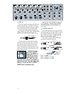
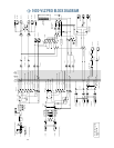
VLZ MIX
ARCHITECTURE
When designing a mixing
circuit, the lowest noise and
best crosstalk specs are achieved by using Very
Low Impedance (VLZ). To implement VLZ in a
mixer, the power supply must be able to de-
liver plenty of current to the circuitry. That’s
why those “wall wart” mixers are often noisy –
they can’t power a VLZ circuit.
At Mackie, audio quality is much more im-
portant than the price of wall warts. All of our
mixers employ VLZ and built-in power supplies
that deliver more than enough current, result-
ing in sonic specifications that rival consoles
upwards of $50,000!
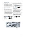
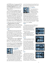
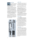
SOURCE MATRIX
Typically, the engineer sends the
MAIN MIX
to an audience (if live) or a mixdown deck (if
recording). But what if the engineer needs to
hear something other than the
MAIN MIX
?
With the 1402-VLZ PRO, the engineer has sev-
eral choices of what to listen to. This is one of
those tricky parts, so buckle up.
Via the
SOURCE
switches, you can choose
to listen to any combination of
MAIN MIX
,
ALT
3-4
and
TAPE
. By now, you probably know
what the
MAIN MIX
is.
ALT 3-4
is that addi-
tional stereo mix bus.
TAPE
is the stereo signal
coming in from the
TAPE IN
RCA
jacks .
Selections made in the
SOURCE
matrix de-
liver stereo signals to the
CONTROL ROOM
,
PHONES
and
METERS
. With no switches en-
gaged, there will be no signal at these outputs
and no meter indication.
The exception to that is the
SOLO
function
. Regardless of the
SOURCE
matrix selec-
tion, engaging a channel’s
SOLO
switch will
replace that selection with the
SOLO
signal,
also sent to the
CONTROL ROOM
,
PHONES
and
METERS
. This is what makes the Level
Setting Procedure
so easy to do.
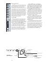
WARNING: Pushing in
both the
TAPE
button (in
the
SOURCE
matrix) and
ASSIGN TO MAIN MIX
can create a feedback
path between
TAPE IN
and
TAPE OUT
.
Make sure your tape deck is not in record,
record-pause or input monitor mode when
you engage these switches, or make sure
the
CONTROL ROOM / PHONES
fader is
fully down (off).
OUTPUT SECTION DESCRIPTION