


15
Owner’s Manual
Owner’s Manual
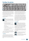
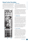
Channel Strip Description
The sixteen channel strips look alike
and function identically. So if you learn
one, you have learned them all. The only
difference is that the eight on the left have
DIRECT OUT [5] jacks and the eight on
the right don’t. We’ll start at the bottom
and work our way up.
“U” LIKE UNITY GAIN
Mackie mixers have a “U” symbol on
almost every level control. This “U” stands
for “unity gain,” meaning no change in
signal level. Once you have performed the
Level-Setting Procedure , you can set every
control at “U” and your signals will travel
through the mixer at optimal levels. What’s
more, all the labels on our controls are
measured in decibels (dB), so you’ll know
what you’re doing level-wise if you choose
to change a control’s settings.
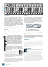
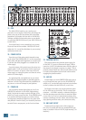
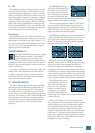
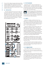
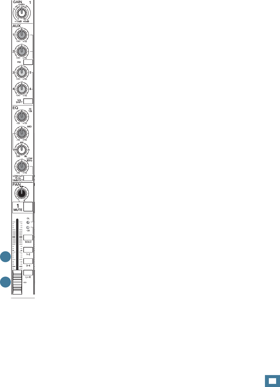
25. CHANNEL FADER
The fader is almost the last control in a
channel’s signal path. It’s placed after the
EQ [32] and MUTE [30] controls (post-EQ
/post-MUTE) and before the PAN [31]con-
trol (pre-PAN). The “U” mark, about three-
quarters of the way up, indicates unity
gain, meaning no increase or decrease of
signal level. All the way up provides an
additional 10 dB, should you need to boost
a section of a song. If you fi nd that the
overall level is too quiet or too loud with a
fader near unity, you’ll want to confi rm the
setting by performing the Level-Setting
Procedure on page 3.
A Clean Fade
Faders are not rocket science — they
operate by dragging a metal pin (the
wiper) across a carbon-based strip (the
track). It is possible for airborne crud to
land on the track. Should that happen, you
may hear scratchy noises or signal drop-
outs as the wiper stumbles over the crud.
Do all you can to keep airborne crud out of your
profession. Use air-conditioned rooms whenever pos-
sible, avoid smoking near the mixer, keep food and drink
away from the mixer, and for pity’s sake, never put the
mixer in your kitchen! We also recommend “exercising”
the faders — give them a few full-travel excursions
once a week or so, and that will help scare the crud
away. Do not use spray cleaners, rather use compressed
air, or a vacuum with brush attachment.
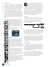
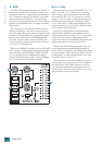
26. ASSIGN (1–2, 3–4, L–R)
Alongside each channel fader are four buttons,
labeled SOLO, 1–2, 3–4 and L–R. The latter three are
collectively referred to as channel assignment switches.
1, 3 and L are the left sides of these stereo pairs, and
2, 4 and R are the right sides. Used in conjunction with
the channel’s PAN [31] knob, these switches determine
the destination of a channel’s signal: With PAN set at
the center detent, the left and right sides receive equal
signal levels. To feed only one side or the other, just turn
the PAN knob accordingly.
If you’re doing a mixdown to a 2-track, simply engage
the L–R switch on each channel that you want to hear,
and they’ll be sent to the main mix. If you want to create
a subgroup of certain channels, engage either the 1–2
or 3–4 switches instead of the L–R, and they’ll be sent
to the appropriate subgroup faders. From there, the
subgroups can be sent back to the main mix, allowing
you to use the subgroup faders as a master control for
those channels.
If you’re printing new tracks or bouncing existing
ones, you’ll also use the 1–2 and 3–4 switches, but not
the L–R switch. Here, you don’t want the subgroups
sent back into the main mix, but sent out, via the SUB
OUTS [8] jacks, to your multitrack inputs. However, if
you’re printing tracks via the DIRECT OUT [5] jacks, all
the channel assignment switches should be disengaged
(up).
The 1604-VLZ3 is what we call a “true 4-bus mixer.”
Each channel can be assigned or unassigned to any of
the subgroups without affecting the other subgroups or
settings within the channel, and each subgroup has its
own master fader and dedicated output. In fact, since
there are 4 subgroups and the main L/R mix, it’s actually
a true 6-bus mixer. We could have named it the 1606-
VLZ3. Darn!
25
26