


20
1604-VLZ3
1604-VLZ3
If you want the subgroup to appear in the center of the
main mix, engage both the ASSIGN TO MAIN MIX, LEFT
and RIGHT switches. The signal will be sent to both
sides, and will be attenuated just enough to preserve
constant loudness, just like the channel PAN [31] knobs
when set in the center.
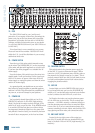
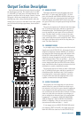
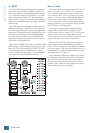
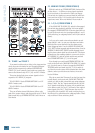
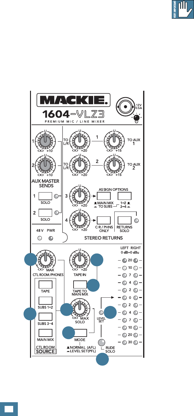
40. TAPE IN (LEVEL)
This knob controls the level of the stereo signal com-
ing from the TAPE INPUT [12] RCA jacks. Its range is
off when fully down, unity at the center detent, with 20
dB additional gain turned fully up, which may come in
handy if you’ve patched in a device with wimpy output
levels. After the level is determined, the stereo tape
signal can be sent to either of two places — the main
mix or the SOURCE [42] matrix .
41. TAPE TO MAIN MIX
Engaging this switch is just like engaging the L-R
switch on a channel — the signal, stereo in this case, is
sent to the main mix. It does not interrupt other signals,
just adds itself to them. This switch can be very handy
in a live sound situation when you want to play soothing
elevator music to an anxious crowd.
WARNING: Engaging TAPE TO MAIN MIX can
create a feedback path between TAPE INPUT
[12] and TAPE OUTPUT [11]. Make sure your
tape deck is not in record, record-pause or input moni-
tor mode when you engage this switch, or that the TAPE
IN [40] level knob is turned fully down.
42. SOURCE
Typically, the engineer sends the main mix to an
audience or to a mixdown deck (if recording). But what
if the engineer needs to hear something other than the
main mix? With the 1604-VLZ3, the engineer has several
choices of what to listen to. This is one of those tricky
parts — have a double espresso fi rst.
Using these switches, you can choose to listen to any
combination of MAIN MIX, SUBS 1-2, SUBS 3-4 and
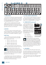
TAPE. Selections made here deliver stereo signals to
the control room, headphones, and meter display. These
signals are tapped off as follows — post-MAIN MIX
FADER, post SUBGROUP FADERS [38], and post-TAPE
IN [40] knob. With no switches engaged, there will be
no signal at these outputs and no meter indication, with
two exceptions: SOLO and STEREO RETURN 4.
Regardless of the SOURCE matrix selection, engag-
ing a SOLO switch will replace that selection with the
SOLO signal, also sent to the control room, headphones,
and meter display. This is what makes the Level-Setting
Procedure so easy.
Now you know how to select the signals you want to
send to the engineer’s control room and/or phones. Once
selected, these signals all pass through the same level
control, aptly named:
43. CTL ROOM/PHONES
As you might expect, this knob controls the levels
of both the stereo control room, and the headphones.
Make sure that you move it to minimum before selecting
or adding a new source.
Whatever your selection, you can also use the control
room outputs for other applications. The sound quality
is just as impeccable as the main outputs. It can be used
as an additional main mix output and this one will have
its own level control. However, should you do this, be
aware that if you engage a SOLO [27] switch, that will
interrupt the mix:
40
41
42
43
44
47
45
46