


15
Owner’s Manual
Owner’s Manual
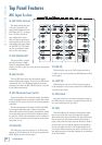
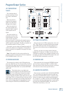
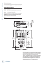
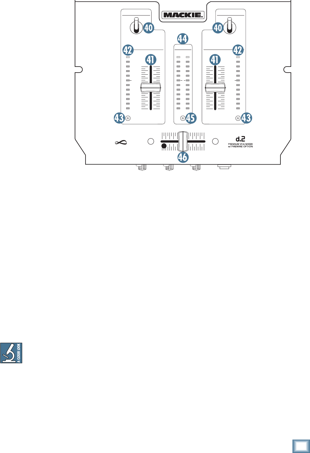
Program Output Section
40. TRANSFORM
Switch
The transform switch
has three positions: Latch-
ing, Center, and Momen-
tary.
When the switch is
Latched, this program’s
signal is on, and passes
through to the outputs.
When the switch is in
the center position, this
program’s signal is muted
at the outputs and FX
Sends.
The other position is a
momentary version of the
Latched position (in other
words, it won’t stay there
when you let go of it), and allows the signal to pass as
long as the switch is held down. Let go of the switch,
and the signal is muted again. This lets you quickly use
the transform switch for “stutter” effects.
If you prefer, you can rotate the Transform switch 45º
or 90º so the switch moves diagonally or horizontally in-
stead of vertically. See Appendix D on page 25 for more
information.
Note: If this switch is in the center position, the
program can still be heard and cued in the headphones
if the PGM/MAIN switch [38] is up.
41. PROGRAM FADER
This controls the volume for the PGM signal being
sent to the Main Mix bus. The characteristics of how the
fader affects the audio signal are determined by the cor-
responding CONTOUR control [47] and the REVERSE
switch [48].
These faders have a very light touch
and are designed to last the lifetime of the
d.2. No audio passes through these faders.
Rather, they send a control voltage to a pair of VCAs
(Voltage-Controlled Amplifi ers) that determine the gain
of the signal. This is a very good thing, by the way, as the
audio will not be affected by any scratchy electrical con-
tacts, and the design allows for customizing the fader
action using the CONTOUR and REVERSE controls.
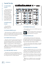
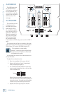
42. PGM LEVEL METERS
These meters have 12 LEDs, ranging from –30 to +20
(OL). They indicate the summed-mono signal strength
of the PGM signals just before the BAL controls [31].
The meters are not affected by the PROGRAM faders
[41].
Typically, you want to see these meters bouncing
between the “0” and the “+4” LEDs. It is okay if the OL
LED lights occasionally, but if it lights frequently or con-
tinuously, turn down the PGM LEVEL control [25] until
the OL LED blinks occasionally or not at all.
43. REVERSE LED
These light when the front-panel REVERSE switches
[48] have been activated for PGM 1 or PGM 2 faders.
They show that the fader direction-of-action is reversed.
(The meters are not reversed, just the faders.)
44. MAIN LEVEL METERS
These meters are similar to the PGM LEVEL METERS
[42], but indicate the signal strength of the Main out-
puts before the MAIN LEVEL control. As with the other
meters, you want to see the signals bouncing between
the “0” and the “+4” LEDs. It is okay if the OL LEDs light
occasionally, but if they light frequently or continuously,
turn down the PROGRAM FADERS [41] until the OL
LEDs blink occasionally, or not at all.
LR
MAIN
BA
OL
10
7
4
2
0
2
4
7
10
20
30
OL
10
7
4
2
0
2
4
7
10
20
30
OL
10
7
4
2
0
2
4
7
10
20
30
TRANSFORM
PGM
2
TRANSFORM
REVERSE
contact-free
cross-fader
infini um
PGM
1
REVERSE REVERSE