


18
PPM608
PPM608
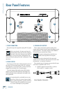
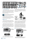
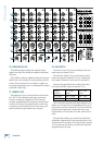
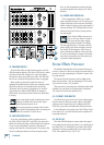
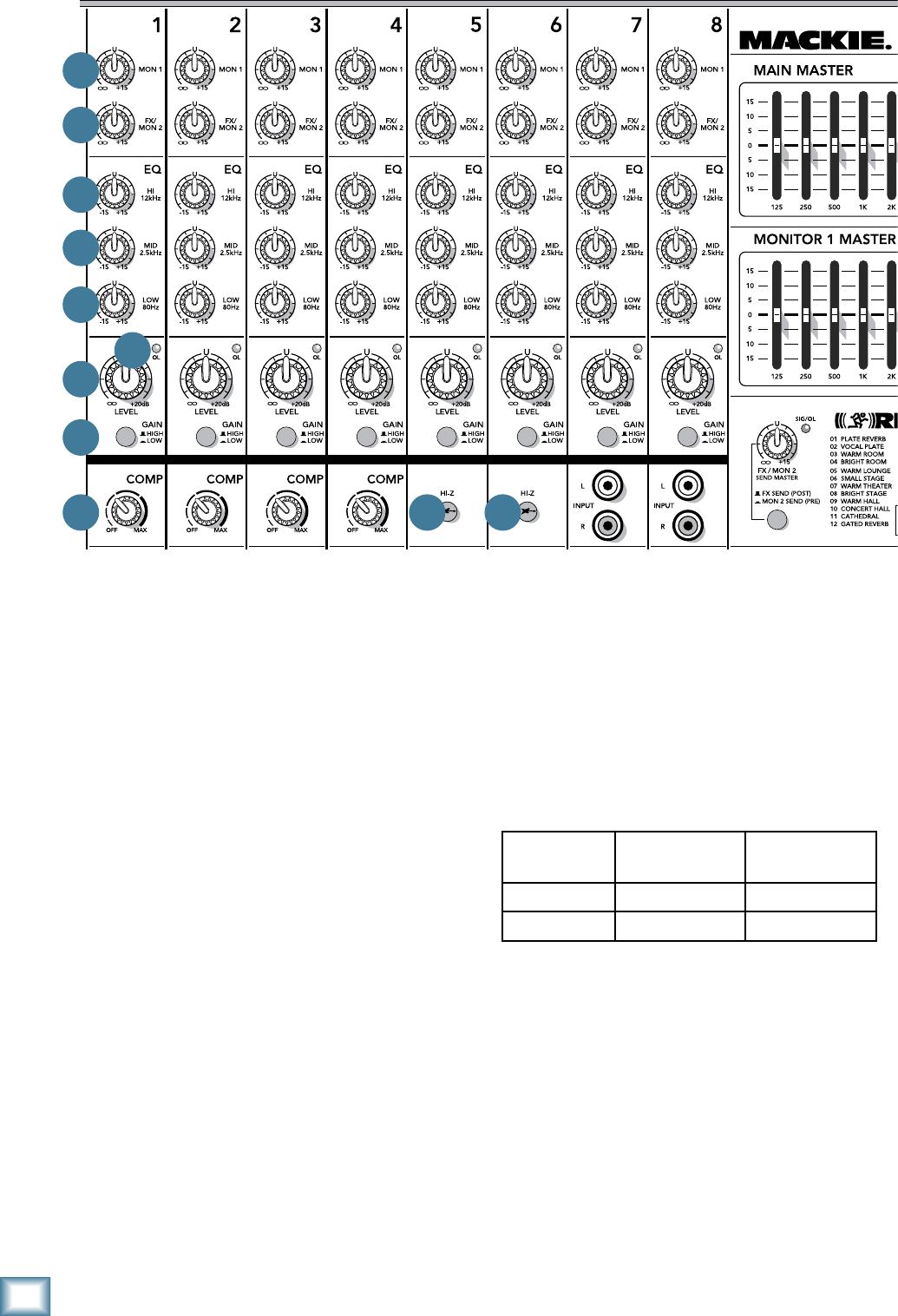
28. GAIN SWITCH
Press this in (low) if you are connecting a line-level
input source to channels 1 to 6.
Press this out (high) if you are connecting a micro-
phone-level signal to channels 1 to 8, or a instrument-
level signal to channels 5 and 6 only (hi-z switch in).
Note that the gain switch has no effect on the line-
level inputs and RCA inputs of channels 7 or 8.
This is the first control that the input signals meet. It
allows you to choose the level depending on the type of
input source you have connected. If it is set incorrectly,
then the input signals may overload the mixer, caus-
ing distortion, or it may come in too low, and be lost in
noise.
The gain switch allows you to make the initial level
adjustment, appropriate for the connected device (mic
or instrument, for example). The channel level controls
[27] are more for fine-tuning, to balance the channels
appropriately for the song.
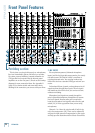
26. OVERLOAD (OL) LED
This LED will come on when the channel’s input
signal is too high. This should be avoided, as distortion
will occur.
If the LED is coming on regularly, check that the gain
switch [28] is set correctly for your input device: Set it
to low if you are using a line-level input, or high if you
are using a microphone input, or instrument-level input
(channels 5 and 6 only).
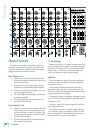
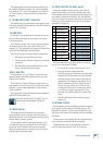
27. CHANNEL LEVEL
This adjusts the level of each channel onto the main
mix. The “U” mark indicates unity gain, meaning no
increase or decrease of signal level. All the way up
provides an additional 20 dB, should you need to boost
a section of the band. If you find that the overall level
is too quiet or too loud with the level near unity, you’ll
want to confirm the gain switch is set correctly.
Switch
position
MIC (XLR)
Inputs
LINE (TRS)
Inputs
IN (LOW) Gain = 25 dB Gain = 0 dB
OUT (HIGH) Gain = 45 dB Gain = 20 dB
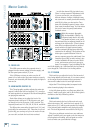
21
22
23
24
25
27
28
29 30
26
30