


26
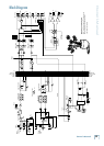
PPM608
PPM608
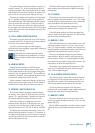
Loudspeaker Cable
Use loudspeaker cables with a minimum conductor
size for the length you need as listed in these tables.
This will minimize
power losses to less
than 0.5 dB. The cable
lengths listed are “up
to” lengths. For in-
between lengths, use
the next larger con-
ductor gauge. Using
larger than the rec-
ommended conductor
size is always permis-
sible. Using smaller
than recommended
conductor size will
result in higher power
losses.
The recommended conductor gauges are listed for
AWG (American Wire Gauge) and Metric WG (Metric
Wire Gauge). Note that smaller AWG numbers = larger
conductors and smaller Metric WG numbers = smaller
conductors. The Metric WG is equal to ten times the
nominal conductor diameter in millimeters.
Longer Lengths
For cable lengths over 200 feet / 60 m at 8 ohms, and
over 100 feet / 30 m at 4 ohms, the conductor sizes need-
ed for less than 0.5 dB power losses are rarely practical
for physical and cost reasons. As a practical compromise
for these situations the recommended conductor gauge
is 10 AWG or 25 metric.
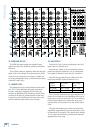
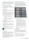
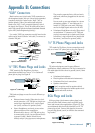
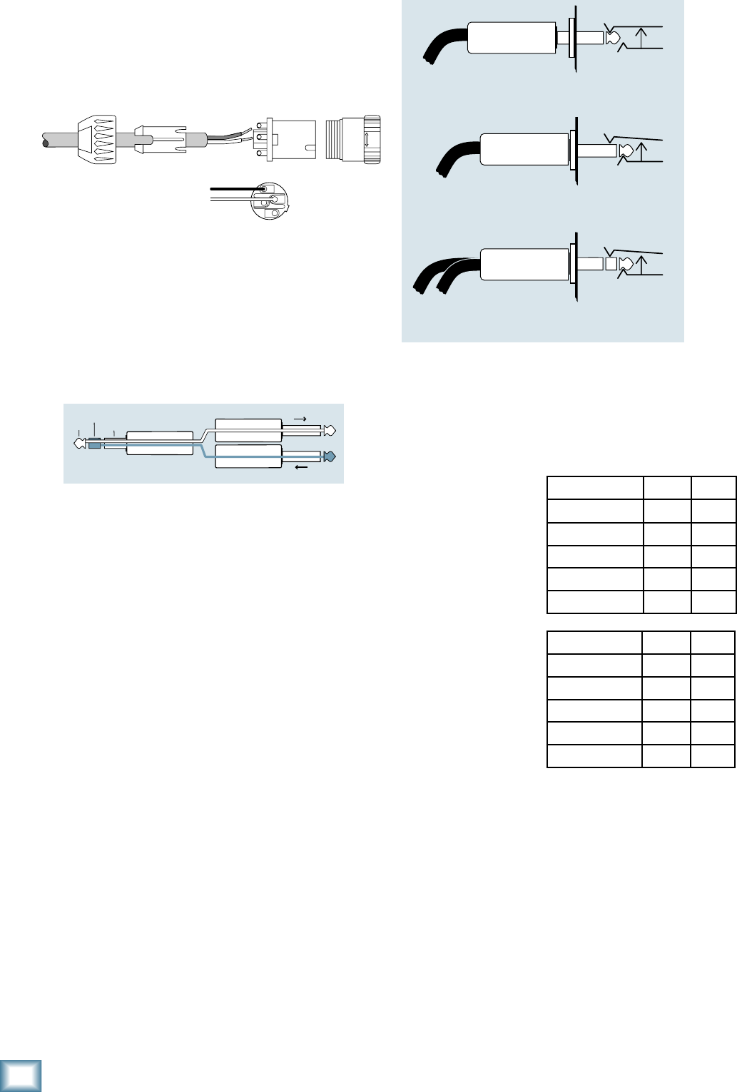
Speakons
When using the Speakon outputs to connect your loud-
speakers, wire the Speakon connectors as shown below:
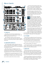
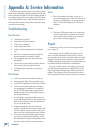
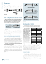
TRS Send/Receive Insert Jacks
Mackie’s single-jack inserts are the three- conductor,
TRS-type 1⁄4" phone. They are unbalanced, but have
both the mixer output (send) and the mixer input
(return) signals in one connector. See Figure F.
The sleeve is the common ground (earth) for both
signals. The send from the mixer to the external unit is
carried on the tip, and the return from the unit to the
mixer is on the ring.
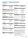
Using the Send-only on an Insert Jack
If you insert a TS (mono) 1⁄4" plug only partially (to
the first click) into a Mackie insert jack, the plug will
not activate the jack switch and will not open the insert
loop in the circuit (thereby allowing the channel signal
to continue on its merry way through the mixer).
This allows you to tap out the channel signal without
interrupting normal operation.
If you push the 1⁄4" TS plug in to the second click, you
will open the jack switch and create a direct out, which
does interrupt the signal in that channel. See Figure G.
NOTE: Do not overload or short-circuit the signal you
are tapping from the mixer. That will affect the internal
signal.
“tip”
This plug connects to one of the
mixer’s Channel Insert jacks.
“ring”
tip
ring
sleeve
SEND to processor
RETURN from processor
(TRS plug)
Figure F
Direct out with no signal interruption to master.
Insert only to first “click.”
Channel Insert jack
Channel Insert jack
Channel Insert jack
Direct out with signal interruption to master.
Insert all the way in to the second “click.”
For use as an effects loop.
(TIP = SEND to effect, RING = RETURN from effect.)
MONO PLUG
MONO PLUG
STEREO
PLUG
Figure G
Figure E
COLD
HOT
1+
1+
1–
1–
2–
2+
Minimum AWG 4 ohm 8 ohm
18 10 ft 25 ft
16 25 50
14 25 75
12 50 125
10 100 200
Min Metric WG 4 ohm 8 ohm
12 3 m 8 m
14 8 15
16 8 25
20 15 40
25 30 60