


28
Basic Operation
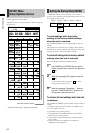
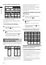
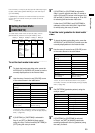
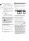
To set the operation of AUX and MIC
faders
Set [AUX/MIC] to [PAIR] or [SEPA.] (separate) using the
rotary 3 control. The operation of each fader varies with the
setting as described in the table shown below.
Setting AUX fader MIC fader
PAIR L and R channels of
AUX input source
L and R channels of
MIC input source
SEPA. L channel of AUX (or
MIC) input source*
1
R channel of AUX (or
MIC) input source*
1
*
1
To adjust the audio level of the microphone, operate the
fader while holding down the SHIFT key.
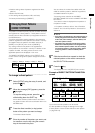
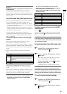
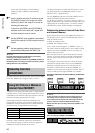
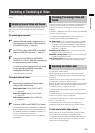
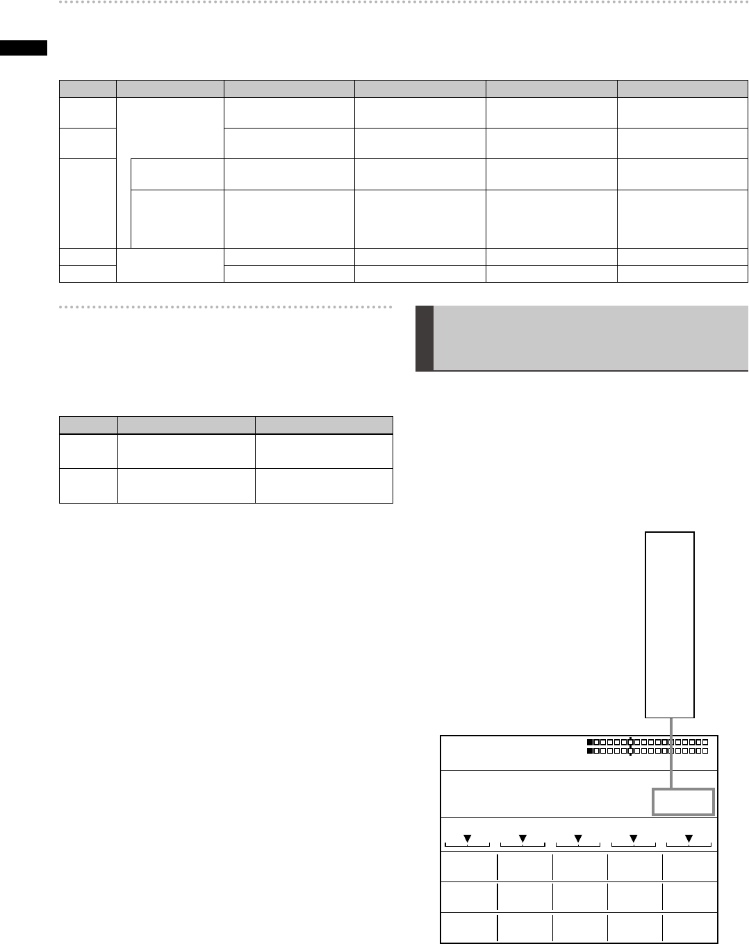
[INT VIDEO] Menu
(Internal Video Setting) Screen
When the INT VIDEO button is pressed, the [INT VIDEO]
menu screen appears as shown below.
This menu is used to set the internal video signal built in
this unit.
During color setting in the [INT VIDEO] menu, the joystick
and rotary Z control are in the color setting mode.
The color set from this menu is indicated in the internal
video display area.
BACK PATTERN GRADE
MODE
WHITE H1 0
WRITEFRAME1
MATTE
BAR
2
255
COLOR
LEVEL
FRAMEPAGE
COLOR
MEMORY
WASH
EVENT
INT VIDEO GRADE POS 80
ME TIME PATTERN INT
00 E
1:00 F 3001
BLUE
PB 128
Y 196
PR 128
WHT
YELW
CYAN
GREN
MGT
RED
BLUE
BLK
CST 1
CST 2
CL BR
ST # *
1
MV # *
1
*
1
# stands for a numeric value. (The maximum value varies
with the memory size (the number of frames) set in the
[MEMORY] submenu of the [SETUP] menu.)
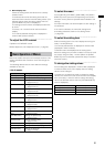
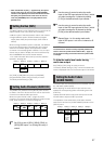
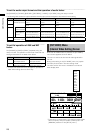
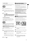
To set the audio output format and the operation of audio faders
Set [SOURCE] to [CP PAIR], [BUS SEP1], [BUS SEP2], [12 PAIR], or [12 SEPA.] using the rotary 2 control.
The following table shows the output method and audio input sources assigned to the faders for each setting.
Setting Output Method SOURCE 1/5 Fader SOURCE 2/6 Fader SOURCE 3/7 Fader SOURCE 4/8 Fader
CP PAIR Sound output of the
selected input source
L and R channels of source
1 (or 5)
L and R channels of source
2 (or 6)
L and R channels of source
3 (or 7)
L and R channels of source
4 (or 8)
BUS SEP1 L channel of A/PROG
source
R channel of A/PROG
source
L channel of B/PRESET
source
R channel of B/PRESET
source
BUS SEP2 When AB bus
system is selected
L channel of A bus source R channel of A bus source L channel of B bus source R channel of B bus source
When Program/
Preset system is
selected
Preview button lighted: L
channel of PROG source
Preview button ashing: L
channel of PRESET source
Preview button lighted: R
channel of PROG source
Preview button ashing: R
channel of PRESET source
Preview button lighted: L
channel of PRESET source
Preview button ashing: L
channel of PROG source
Preview button lighted: R
channel of PRESET source
Preview button ashing: R
channel of PROG source
12 PAIR
Fixed to sound of
input sources 1 and 2.
L and R channel of source 1 L and R channel of source 2
Not available Not available
12 SEPA. L channel of source 1 R channel of source 1 L channel of source 2 R channel of source 2