


10
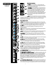
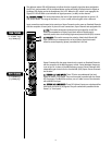
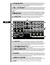
4455.. LLEEFFTT//RRIIGGHHTT LLEEVVEELL DDIISSPPLLAAYYSS
These indicators graphically display the signal level being sent to
the Left or Right outputs (L, R). Signal is sampled at the summing amp and post-master faders to
monitor clipping throughout the Left/Right and Mono Master section. The Clip indicator will
illuminate when signal approaches clipping (-2 dB).
4466.. MMOONNOO —— AAFFLL//PPFFLL LLEEVVEELL DDIISSPPLLAAYY
This indicator graphically displays the signal level being sent
to the Mono output. When any AFL/PFL switch on the mixer is activated, this display indicates the
signal level being sent to the AFL/PFL bus. The AFL/PFL indicator flashes if either mode (AFL or PFL)
is selected.
NNOOTTEE::
Clip LED can illuminate before the rest of the array indicating the summing amp is clipping.
4477.. MMOONNOO MMAASSTTEERR FFAADDEERR
This control determines the level of the output signal sent to the Mono
output. An adjacent switch allows a post-fader signal to be sent to the Headphone Output and the
AFL/PFL Level Display. A yellow LED above the switch indicates AFL (post-fader) engagement.
4488.. LL && RR MMAASSTTEERR FFAADDEERRSS
These controls determine the level of the signal sent to the Left and
Right outputs respectively. As with all faders, the optimum setting is at unity gain (0).
(BAL)(BAL)(BAL)
(UNBAL) (UNBAL) (UNBAL)
L
R
M
MONO/
LEFT
T=IN
R=OUT
RIGHT
INSERT
(TRS)
INSERT
(TRS)
INSERT
(TRS)
70 WATTS
100V -240V
(BAL)
(UNBAL)
(BAL)
(UNBAL)
(BAL)
(UNBAL)
(BAL)
(UNBAL)(UNBAL)
T=IN
R=OUT
T=IN
R=OUT
T=IN
R=OUT
MONO/
LEFT
RIGHT
(UNBAL)
POWER
50/60 Hz
3
SUB 1
OUT
SUB 2
OUT
SUB 3
OUT
SUB 4
OUT
RIGHT
OUT
LEFT
OUT
MONO
OUT
RETURN 1
RIGHT
LEFT
MONO
AUX 2
OUT
AUX 1
OUT
AUX 3
OUT
AUX 4
OUT
AUX 5
OUT
AUX 6
OUT
RETURN 2
COMP4
I/O
COMP3
I/O
COMP2
I/O
COMP1
I/O
(UNBAL) (UNBAL) (UNBAL) (UNBAL)
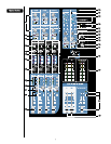
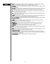
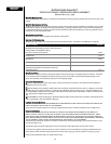
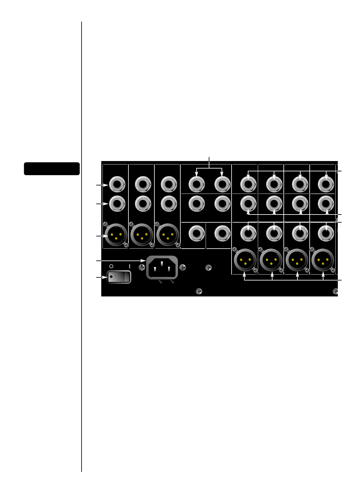
RReeaarr PPaanneell
4499.. LL,, RR,, MMOONNOO IINNSSEERRTT
These 1/4" stereo (TRS) jacks, provided on the Left, Right, and Mono
channels, allow an external device to be inserted into the signal path, pre-master fader. The tip
carries the signal being sent and the ring is the signal return. A switch in the jack connects the send
to the return if no plug is inserted. The signal must be returned to this jack when this feature is
used. Failure to return the signal will result in no output.
5500.. LL,, RR,, MMOONNOO UUNNBBAALL ((UUNNBBAALLAANNCCEEDD OOUUTTPPUUTT))
These 1/4" jacks allow output of an unbalanced
signal and are provided for the Left, Right, and Mono channels.
5511.. LL,, RR,, MMOONNOO BBAALL ((BBAALLAANNCCEEDD OOUUTTPPUUTT))
These XLR connectors allow output of a balanced signal
and are also provided for the Left, Right, and Mono channels. The unbalanced and balanced outputs
can be used simultaneously, but both output levels are controlled by the corresponding Master
fader.
5522.. RREETTUURRNN IINNPPUUTTSS
These 1/4" balanced (TRS) high-impedance inputs can be used as stereo or
individual returns. Designed for effects return, they can also be used as additional stereo inputs. The
Mono/Left input provides signal to both inputs if no connector is attached to the Right jack. The tip
is the positive input for both balanced and unbalanced use.
5533.. CCOOMMPPRREESSSSOORR II//OO ((IINNPPUUTT//OOUUTTPPUUTT))
These 1/4" stereo (TRS) jacks allow the internal
compressors for each Sub group to be patched to an input channel or to an external device. The tip
carries the input (return) signal to the compressor and the ring carries the output (send).
5544.. SSUUBB OOUUTT
These 1/4" (TRS) unbalanced outputs provide signal from the Sub groups.
4499
5500
5511
5577
5588
5566
5555
5533
5522
5544