


5
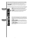
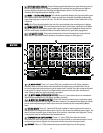
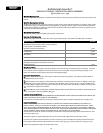
RReeaarr PPaanneell CCoonnnneeccttiioonnss
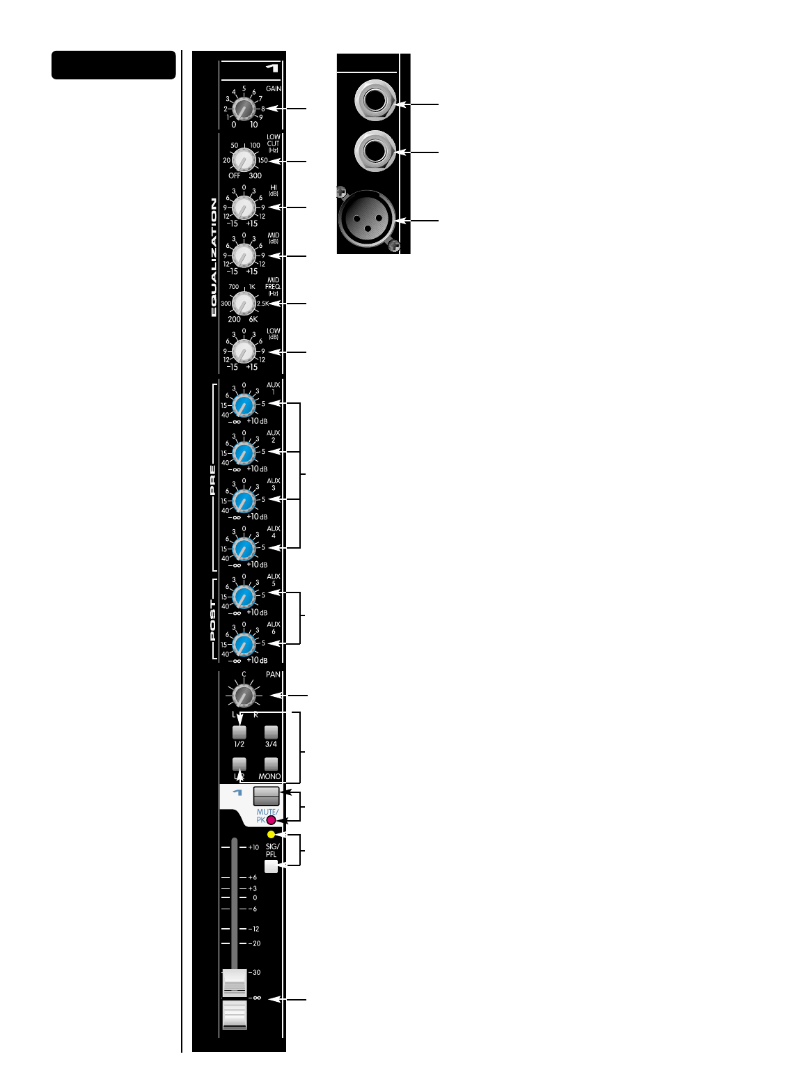
11.. IINNSSEERRTT
This is a female 1/4" TRS connector for
terminating two, single-ended (unbalanced) line level
circuits. The tip is a line output.
22.. LLIINNEE ((BBAALL))
This is a female 1/4" TRS connector for
terminating balanced lower high impedance line level
circuits. Tip is positive, ring is negative. This circuit is
wired in parallel with the female XLR connector. This
input is connected through a 20 dB pad to the Mic
input. Connecting to this input will not disable the XLR
input connector, so both inputs should NOT be used
simultaneously.
33.. MMIICC
This is a female XLR connector for terminating
balanced, low impedance microphone circuits. Pin 2 is positive and +48 V DC
is applied to pins 2 and 3 via a resistive network when the front panel
Phantom Power switch is ON.
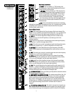
CChhaannnneell SSttrriipp CCoonnttrroollss
44.. GGAAIINN
This control adjusts the first gain stage of the input channel. The
range is +10 to +56 dB for microphone level inputs and -10 to +36 dB for line
level inputs. The output of this gain stage also drives the SIG/PFL LED.
55.. LLOOWW CCUUTT
This control adjusts the setting of the low cut filter and is
variable from no cut in the OFF position, to cut below 300 Hz in the
maximum position.
66.. HHII
This active tone control is a shelving-type that varies high-frequency
response by +/-15 dB in the range above 12 kHz.
77.. MMIIDD
This active tone control is a bandpass (peak/notch) type that varies
mid frequency response by +/-15 dB in a range from 200 Hz to 6 kHz.
88.. MMIIDD FFRREEQQ
This control determines the center frequency of the MID
control. Center frequency for the bandpass filter can be set from 200 Hz to
6 kHz.
99.. LLOOWW
This active tone control is a shelving-type that varies low frequency
response by +/-15 dB. Corner frequency is 75 Hz.
1100.. AAUUXX 11 -- 44
These controls adjust the level of the channel’s pre-fader
signal that is sent to the auxiliary mix. Gain is variable from minus infinity
(– ∞) to +10 dB. Unity gain is at the center detent position.
1111.. AAUUXX 55 -- 66
These controls adjust the level of the channel’s post-fader
signal that is sent to the auxiliary mix. Gain is variable from minus infinity
(-∞) to +10 dB. Unity gain is at the center detent position.
1122.. PPAANN
This control determines the signal’s position with respect to L/R
and Sub 1 - 4 outputs. Rotating the control counterclockwise increases the
amount of signal sent to L and odd-numbered Subs; rotation clockwise
increases the amount sent to R and even-numbered Subs.
1133.. AASSSSIIGGNN SSWWIITTCCHHEESS
These post-fader, post-EQ switches determine where
the channel signal is being sent.
1144.. MMUUTTEE SSWWIITTCCHH aanndd MMUUTTEE//CCLLIIPP LLEEDD
This switch mutes all Aux, Sub, L/R,
and Mono sends from the corresponding channel. The switch is equipped
with a red LED that will illuminate when the channel is muted. When the
Mute switch is disengaged, the LED functions as a clip (PK) indicator that
will illuminate at 2 dB below clipping. Muting the channel does not prevent
the PFL signal from being sent to the PFL mix when the PFL switch is
engaged.
1155.. PPFFLL SSWWIITTCCHH && SSIIGGNNAALL//PPFFLL LLEEDD
This switch connects the channel’s pre-
fader signal to the PFL mix. With this feature engaged, the channel’s signal
can be monitored through the headphones and/or on the AFL/PFL display.
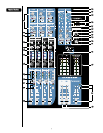
SSttaannddaarrdd CChhaannnneellss
INSERT
MIC
(TRS)
(BAL)
LINE
(BAL)
1
11
1 - 20 (AAM
™
2443)
1 - 28 (AAM3243)
44
55
66
77
88
1122
99
1166
1100
22
33
1111
1144
1155
1133