


8
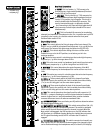
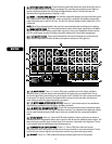
AAuuxx SSeennddss
2211.. LLEEVVEELL
This control sets the output level of the various Aux mixes and is adjustable from no
output (– ∞) to +10 dB.
2222.. MMUUTTEE SSWWIITTCCHH && MMUUTTEE//CCLLIIPP LLEEDD
This switch mutes the output signal from the respective Aux
Send. Illumination of the corresponding red LED signifies this status. When the Mute switch is
disengaged, the LED functions as a clip (PK) indicator that will illuminate at 2 dB below clipping.
2233.. AAFFLL SSWWIITTCCHH && AAFFLL//SSIIGGNNAALL LLEEDD
This switch directs the post-fader (AFL) signal to the
Headphone Output, and activates the AFL/PFL LED display. An adjacent LED illuminates to signify
this selection. If AFL is not selected, the LED will blink as an indication of signal presence (-20 dBu).
Selecting AFL allows monitoring of Aux Sends with the full AFL/PFL Level Display, as well as allowing
the operator to hear the output.
CCoommpprreessssoorrss
The compressors on the AAM 2443/3243 function similarly to automatic volume controls. In other
words, they put signals into a more controllable dynamic range. For example, suppose a singer sings
too softly and gets buried in the mix on certain parts of a song, yet sings real loudly on other parts.
To control this problem, the operator must “ride gain” (turn the volume up and down to achieve a
constant level), but these dynamic changes may be hard to anticipate. Using a compressor
eliminates this problem. The compressors are factory set at a ratio of 4 to 1, meaning that for every
4dB of change in input signal, the output changes 1 dB. Compression takes place once the level
determined by the Threshold control is reached. A high setting, rotating the control clockwise, will
result in only the louder notes being compressed; a low setting, rotating the control
counterclockwise, will compress a broader range of notes.
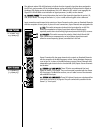
2244.. CCOOMMPPRREESSSSOORR II//OO
This switch determines if the compressor will be used on the Sub mix or will
be patched to another channel or external location. The corresponding yellow LED illuminates when
the compressor is being patched externally. This switch can also be used to perform the bypass
function. When the compressor is assigned to the Sub group, the Input/Output jack on the rear
panel is bypassed. Similarly, when the compressor is being patched externally, the Sub group is
bypassed. Engaging the I/O switch allows the operator to hear the difference between the
compressed and noncompressed signal when the compressor is being used on the Sub group.
2255.. GGAAIINN
This control sets the output level of the compressor and allows recovery of gain lost by
compression. The amount of gain being lost will be represented on the Gain Reduction LEDs, and a
similar setting on the Gain control will approximate pre-compression levels.
2266.. LLIINNKK
This switch allows the compressor in Sub group 1 (or 3) to be linked with the compressor
in Sub group 2 (or 4). This is useful if the two Sub groups are being used to create a stereo image.
When they are linked, the RMS detector voltages are summed together for an accurate
representation of the two levels. This locks the compressors together to maintain the stereo image
during compression. While linked, the controls in the first of the two linked groups affect both
channels. The compressor controls in the second group are disabled. The gain reduction meter for
the first group is accurate for both groups and should be used to monitor compressor activity. When
the link is enabled the yellow LED will illuminate.
NNOOTTEE::
While linked, the gain reduction meter in the second group may show gain reduction,
although it is not a true representation of the compressor activity.
2277.. GGAAIINN RREEDDUUCCTTIIOONN LLEEDDss
These LEDs graphically show the amount of gain being reduced through
compression (-1 to -12 dB).
2288.. TTHHRREESSHHOOLLDD
This control sets the level at which compression activates and is variable from
-30 dBu to no compression in the OFF position. The adjacent LED (0 dBu) will illuminate when
enough signal is present for compression to function properly.
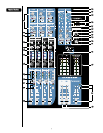
SSuubb GGrroouuppss
2299.. LLEEVVEELL LLEEDDss
This display indicates the amount of signal present in the Sub group mix. Signal is
sampled at the summing amp and post-master faders to monitor clipping throughout the Sub group.
The Clip indicator will illuminate when signal approaches clipping (-2 dB). For example, the Sub
fader may be at an acceptable setting, yet the channel signals assigned to the Sub may be
approaching clipping. If this is occurring, the channel fader and gain settings may need to be
assessed and setting corrections made.