


9
NNOOTTEE::
The CLIP LED can illuminate before the rest of the array indicating the summing amp is
clipping.
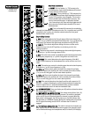
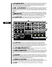
3300.. LLEEFFTT,, RRIIGGHHTT,, MMOONNOO ((OOUUTTPPUUTT AASSSSIIGGNN))
These switches determine where the Sub mix signal is
being sent. For example, if each individual drum mic is assigned to Sub 1, depressing the Left button
will send the drum Sub mix to the Left Out on the rear panel.
3311.. MMUUTTEE//MMUUTTEE LLEEDD
This switch mutes all output from the corresponding Sub group. Illumination
of the adjacent red LED occurs when the Mute button is depressed.
3322.. AAFFLL//AAFFLL LLEEDD
This switch directs the post-fader signal from the respective Sub group to the
Headphone Output and to the AFL/PFL Level Display.
3333.. SSUUBB FFAADDEERR
This control determines how much signal is present at the selected output. As with
channel faders, optimum setting is at unity gain (0). If the output level is too quiet or too loud at
unity gain, the gain and fader settings on the channels assigned to the Sub mix should be checked.
If two Sub mixes, Sub 1 and Sub 2 for example, are intended to be in stereo, adjust both Faders
equally and simultaneously to preserve balance.
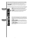
RReettuurrnnss
3344.. PPOOWWEERR LLEEDD
This green LED will illuminate when power is applied to the console, indicating the
unit is on.
3355.. LLOOWW CCUUTT
This switch activates the low-cut (150 Hz -18 dB/per octave) filter. With this feature
engaged, input frequencies below 150 Hz will be rejected. Especially when using reverb, the low-cut
filter is useful in reducing “low-end rumble” and making resultant sounds less “muddy.”
3366.. AAUUXX 11 && AAUUXX 22
These controls determine the level of the signal returned to the respective Aux
bus, allowing musicians/singers to hear external effects.
NNOOTTEE::
Do not use AUX SENDS 1 or 2 as the path to external equipment that is to be sent back to the
corresponding AUX mix (1 or 2) due to the creation of an electronic feedback loop.
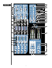
3377.. 11//22,, 33//44,, LL//RR,, MMOONNOO ((AASSSSIIGGNN))
Like the channel assign switches, these buttons determine the
bus assignment of the input signal. They determine where the return signal is being sent.
3388 BBAALL//PPAANN
This control determines the placement of the signal in its assigned bus. Rotating the
control counterclockwise (L) sends more signal to the Left output and odd-numbered Subs; rotating
clockwise (R) sends more signal to the Right output and even-numbered Subs. The C position sends
equal amounts to each.
3399.. LLEEVVEELL
This control determines the level of the signal being sent to its assigned bus(es). It
functions similarly to the channel faders.
4400.. MMUUTTEE SSWWIITTCCHH && MMUUTTEE//CCLLIIPP LLEEDD
Like the other mutes on the console, this switch interrupts
the input signal being sent to the bus(es). Red LED illumination indicates activation. When Mute is
not engaged, the LED functions as a clip (PK) indicator that illuminates at 2 dB below clipping.
4411.. AAFFLL SSWWIITTCCHH && AAFFLL//SSIIGGNNAALL LLEEDD
This switch directs the post-fader (AFL) signal to the
Headphone Output, and to the AFL/PFL Level Display. An adjacent LED illuminates to signify this
selection. If AFL is not selected, the LED will blink as an indication of signal presence (-20 dBu).
4422.. PPHHAANNTTOOMM PPOOWWEERR
These switches apply power (+48 V DC) to the Mic (XLR) inputs on channels
1–16 and 17–24 respectively (1–24 and 25–32 on the AAM 3243). This feature provides power to
microphones that need an external power source. These switches are recessed into the console and
require a small “tool” to activate. If Phantom Power is used, do not connect unbalanced dynamic
microphones or other devices that cannot handle this voltage to the XLR inputs. (Some wireless
receivers may be damaged. Consult their manuals.) A regular low-impedance mic will not be
harmed. The Line inputs are not connected to the +48 V supply and are safe for balanced or
unbalanced inputs. An adjacent LED will illuminate when Phantom Power is activated on its
respective channels.
4433.. HHEEAADDPPHHOONNEE OOUUTTPPUUTT
This stereo output jack (TRS) provides the signal to drive headphones.
Signal to this output is L/R unless AFL or PFL is activated.
4444.. HHEEAADDPPHHOONNEE LLEEVVEELL
This control adjusts the volume of the signal being sent to the Headphone
Output.