


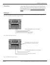
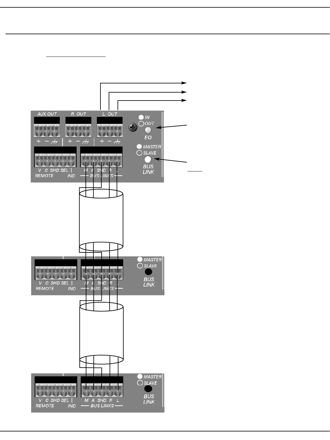
Slave Mixer 2
Slave Mixer 1
SMR 821 User Manual
Page 10
http://aa.peavey.com copyright 2000 All Rights Reserved
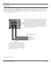
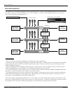
Audio Positive
Audio Negative
Shield
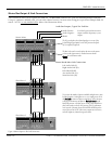
Audio Bus Outputs, Typical For Each Bus
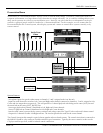
Left Audio Link (L)
Right Audio Link (R)
Link Shield (SHD)
Master Bus & Mute Link Connections
Aux Audio Link (A)
Mute Bus Link (M)
Master Bus Output & Link Connections
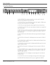
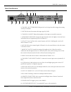
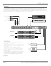
These connectors allow you to expand your SMR 821. The Bus Links connector has 5 pins for combining multiple SMR 821’s.
Using a 4-conductor, shielded cable, you can easily connect between 2 or more units wiring pin-to-pin across multiple SMR 821
mixers. NOTE: Use only shielded cable!
Refer to the illustrations below.
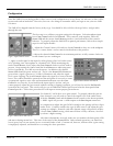
The Bus Link switch is used to place the mixer in the master
or slave mode of operation. A stand-alone unit should
always
be in the master mode.
The EQ switch places the 4-band equalizer in or out of the
Left and Right signal paths. In the OUT position the equal-
izer is completely bypassed.
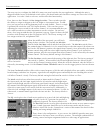
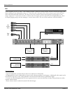
To increase the number of inputs available, multiple mixers may
be linked together. Linking mixers is a very simple process. Wire
the
Bus Links
connections between each mixer. Select the mixer
to be used as the master and place its
Bus Link Switch
in the
MASTER position. All other mixers in the system should have
their link switches in the SLAVE position. The EQ and master
level controls of the unit chosen as MASTER should be used to
control the system. NOTE: Slave mixer outputs are still active,
and will output any channels assigned to them.
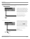
Master Mixer
In a linked system, the Master mixer’s
outputs would be the primary system
outputs.
Figure 4. Master Output & Bus Link Connections