


SMR 821 User Manual
Page 12
http://aa.peavey.com copyright 2000 All Rights Reserved
Since the SMR 821 is an analog product, there is not a lot of configuration to worry about. No software, no data cables,
no networks and no headaches. However, there are a few things to remember while you begin to use your new SMR
821 mixer.
The SMR 821 is shipped from the factory ready to go. You should be able to follow the steps below, and get audio
through the unit.
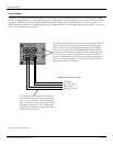
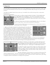
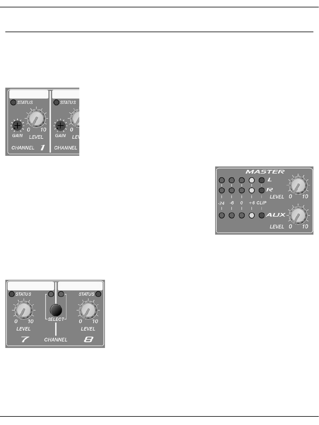
The first step is to calibrate your gain settings for the inputs. Each microphone input
has a Gain Control and a Level Control. These controls work together, while the
Status LED and the master Level Meters provide a visual indication of the control’s
behavior. To properly adjust the SMR 821 for optimal performance, follow these simple
steps for each input channel:
1. Adjust the Channel, Master L/R and Aux Level Controls so they are at the midpoint.
There is a “center detent” on the control which indicates this position.
2. Adjust the channel Gain Control to its minimum position, or fully counter-clockwise
for the channel you are working on.
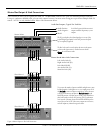
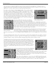
3. Apply an audio signal to the input by either playing a line level audio source
or by speaking into a microphone at a nominal level. While monitoring the
master Level Meters, slowly adjust the Gain Control clockwise while audio is
present. Keep turning the control until the Level Meters are indicating nomi-
nal level around the -6 to 0dB area on the meters. In addition, the channel
Status LED should be green and not red. The bi-color Status LED illuminates
green when a signal is present at -20 dBu. It illuminates red when the signal
level is near clipping. The Level Control adjusts the signal level sent to the mix
buses. This control should be operated near the mid-point of its travel to assure
an optimized signal-to-noise ratio and maximum headroom, once the Gain
Control is set correctly. If you find that the input signal is too hot, and you
cannot properly adjust the gain control without causing a clipping condition, you will need to use the Pad Switch,
located on the rear panel. This switch will give you an additional 20dB of pad beyond what the front panel Gain
Control provides. Follow this procedure for each input to ensure proper gain structure.
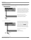
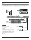
For channels 7 and 8, there is no gain control. To properly adust the gain on
these channels, you will need to control the output level of the audio source.
With the Channel Level and the Master Level controls at the detent position,
a -10dBV signal will present a +4dBu output at the Bus Output connectors.
It is important to adjust the gain DOWN enough so the preamp will not clip at
louder levels. Carefully consider the type of audio source, and adjust the gain
settings accordingly. Material with wide dynamic range will generally require
a lower Gain Control setting, while material that is fairly constant, can usual-
ly tolerate a higher setting.
After these adjustments are made, make sure you monitor the front panel LED’s
and meters during normal use. Take note of the action of the Status LED’s. Under normal operation, you should see
lots of green, but it is not unusual to see occasional flashes of red. Constant red, however, indicates that a gain setting
is improperly adjusted, and should be re-set using the above procedure.
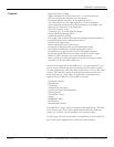
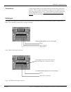
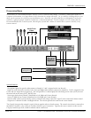
Configuration
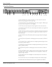
Figure 7. Input Channel Controls
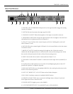
Figure 8. Master Meters and Controls
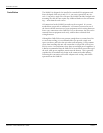
Figure 9. Master Meters and Controls