


Options & Modifications
Page 23Peavey Electronics Corp
Optional Features
Installing the Optional Microphone Input Transformers
The SMR 821 offers optional features for specific job requirements. These
options include Transformers for the microphone inputs and the ability to
defeat the functionality of the Channel 7/8 select switch.
These options and modifications require access to the inside of the SMR
821. It is highly recommended that the installation of the optional
microphone transformers and the modification of the Channel 7/8 select
switch be performed by qualified service personnel. There are danger-
ous voltages present inside the unit, as well as static sensitive compo-
nents. Damage to the SMR 821’s internal circuitry caused by un-quali-
fied persons is not covered under warranty, and in fact, could void the
warranty altogether.
Optional transformers for use with the microphone input circuits are available from Peavey Electronics Corp. (part #
70500852). The optional transformers may be added one at a time, all at once, or in any combination. To ensure that the trans-
formers are properly installed, please refer to the instructions and illustrations in this section. If you have ANY questions, or
are not sure about it, do not hesitate to call our Tech Support Group.
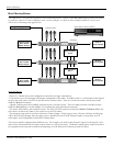
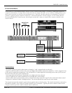
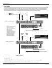
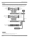
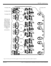
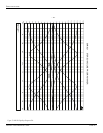
Refer to Figure 14. “Cutaway of circuit board showing jumper locations for installation of optional microphone transformers”
while performing the following steps:
1. Unplug the SMR821 from the AC voltage source.
2. Remove the 6 screws securing the top panel of the SMR821. Remove the top and set aside.
3. Remove the 5 screws securing the rear panel to the chassis.
4. Remove the 5 screws securing the front panel to the chassis.
5. Carefully turn the SMR821 upside down.
6. Remove the 11 screws securing the circuit board assembly to the chassis.
7. Carefully turn the entire SMR821 right side up. One end of the circuit board assembly (with the front and rear panels still
attached) can be lifted out of the chassis with power supply wires still intact to access the bottom side of the circuit board.
8. Locate the six round transformer outlines.
9. Before installing the transformers, you will need to cut some jumpers and resistors. These components are labeled with refer-
ence designators on the board.
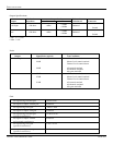
10. For each transformer installed, three jumpers and one resistor will need to be cut. The following table shows which compo-
nents need to be cut for their corresponding transformer.
11. The transformers can only be inserted into the board one way. Place a transformer into the circuit board and solder in place.
Repeat for each transformer being installed.
Re-installing the Circuit Board and Re-assembling the Unit
1. Place the circuit board assembly (with the front and rear panels still attached) into the chassis.
2. Carefully turn the SMR821 upside down and replace the 11 screws securing the circuit board assembly to the chassis.
3. Carefully turn the unit right side up.
4. Replace the 5 screws securing the front panel to the chassis.
5. Replace the 5 screws securing the rear panel to the chassis.
6. Place the top panel on the chassis and replace the 6 screws securing it to the chassis.
Transformer T101 T1201 T301 T401 T501 T601
Components
to be cut
J102, J103,
J105, R116
J202, J203,
J205, R216
J302, J303,
J305, R316
J402, J403,
J405, R416
J502, J503,
J505, R516
J602, J603,
J605, R616
!