


Configuration
Page 13Peavey Electronics Corp
The next step is to configure the SMR 821’s many rear panel switches for your application. Although the unit is
shipped from the factory with default switch values, you should make sure that these settings are correct for YOUR
application. Let’s take a look at each one, and describe their functionality.
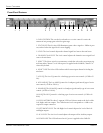
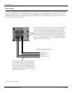
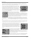
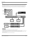
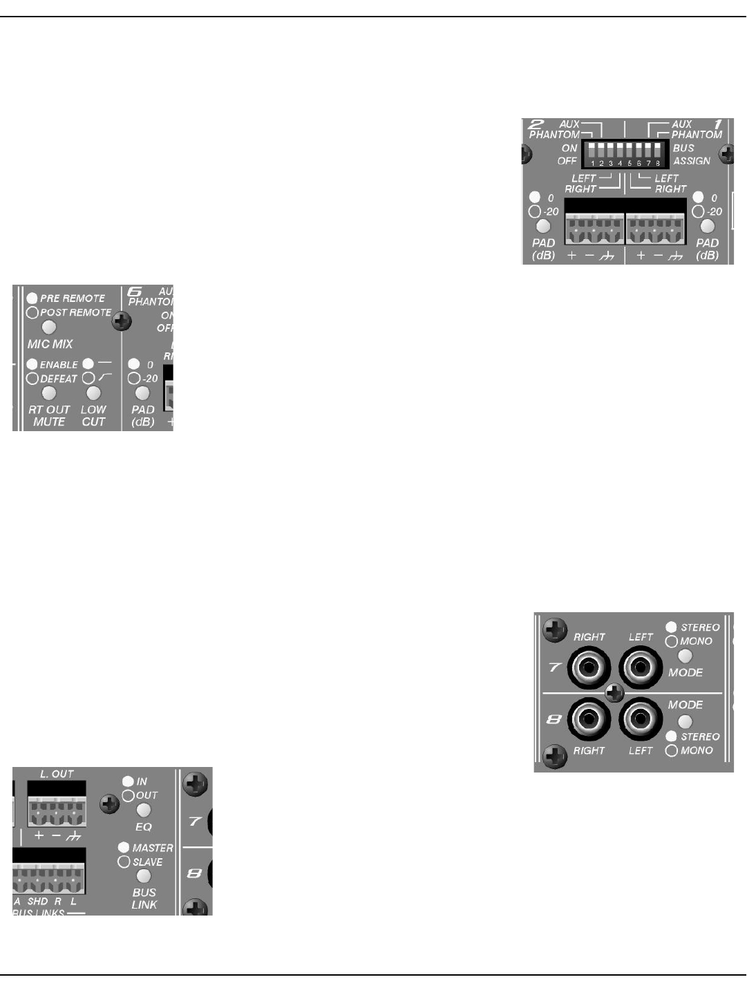
First, there are the Channels 1-6 Bus Assign Switches. These switches provide
the ability to assign each input to the Left, Right or Aux output buses. In addi-
tion, you can turn on or off the phantom power on each channel. There is a single
8-position DIP switch for each TWO input channels. Take care that you are
adjusting the correct switch for the correct channel. It is recommended that you
use a small screwdriver or other instrument to set the switches. Do not force
them. Also, keep in mind that the ON position is on top. Figure 10 shows the DIP
switches with all functions in the ON position. NOTE: The factory setting is all
bus assign switches ON, and phantom OFF.
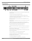
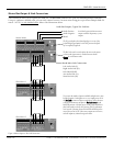
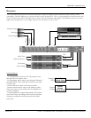
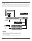
About the middle of the rear panel, you will find a
group of three switches. They include the Mic Mix
switch, the Rt Out Mute switch and the Low Cut switch. The Mic Mix switch allows
the summed signal of Channels 1-6 to be routed before or after the remote L/R volume con-
trol. In the “Pre Remote” position, the signals from Channels 1-6 are affected by the remote
volume control along with the stereo input from the either Channel 7 or 8. In the Post
Remote position, only the stereo input from either Channel 7 or 8 is affected by the remote
volume control. The factory default setting is “Pre-Remote”.
The Rt Out Mute switch controls the muting of the right mix bus. The factory setting of
this switch is “Enable”. When enabled, the left and right mix buses are affected by the
activity of the Channel 1 muting circuit. When this switch is defeated, only the left bus is
affected by the muting circuit. Use the Channel 1 Mute Threshold control to set the trigger point to activate the mut-
ing.
The Low Cut Switch enables a filter with a corner frequency of 100 Hz and is helpful to filter out rumble, wind noise,
breath thumps, and other low-frequency signals that rob amplifier power and muddy the mix. Enabling this switch
will affect Channels 1-6 only. The factory default setting for the Low Cut switch is “Defeat” or “Flat”.
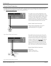
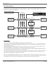
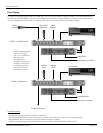
The Mode switch selects either Stereo mode or Mono mode for Channel 7 or 8. In
the Stereo mode, the Left input signal feeds the Left mix bus and the Right input
signal feeds the Right mix bus via the front panel Level control. In the Mono mode,
the summed Left and Right input signals feed both Left and Right mix buses. This
allows for a mono source to be used to feed the stereo mix buses. Additionally, it
allows for Left and Right outputs of the source to be summed without a Y-cable. In
either mode, a summed mono signal feeds the Aux mix bus. The factory default is
“Stereo”.
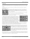
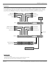
The EQ switch places the 4-band stereo equalizer in or out of the Left and Right sig-
nal paths. In the OUT position the equalizer is
completely bypassed. The factory default is IN.
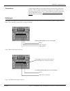
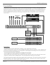
The Bus Link switch is used to place the mixer in the master or slave mode of opera-
tion. A stand-alone unit should always be in the master mode, and the factory
default is MASTER. See the “Connections” section of this manual for details on Bus
Linking and using multiple SMR 821’s.
That’s about it for configuration. As you can see, the SMR 821 provides many pow-
erful features for better, more cost effective systems. The multiple combinations of
routing, control and input assignment facilitate a wide range of applications.
Figure 10. Input Channel Bus Assign
Switches and Input Connectors
Figure 11. Mic Mix, Rt Out Mute
and Low Cut Switches
Figure 12. Channel 7 & 9 Mode Switches
Figure 13. Channel 7 & 9 Mode Switches