


Connections
Page 11Peavey Electronics Corp
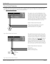
External Control Connections
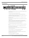
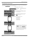
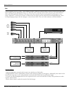
Figure 6. Remote Channel 7/8 Select Connections
Remote Volume Control Connections
This example shows the connection for remote selection of the
Channels 7 or 8 input select feature. The selection is done by con-
necting a momentary switch between SEL and SHD. Each time
the switch is actuated, the channel selection is toggled and alter-
nated between Channel 7 and 8. This remote operation functions
in conjunction with the front panel
Select Control
. A bi-color
LED or 2 individual LEDs may be connected as shown in the
diagram for remote indication of the selected stereo line input.
NOTE: The IND circuit can supply a maximum of 6ma for the
LEDs’. Take care that you do not exceed this current limitation.
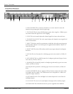
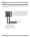
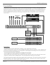
Volume Control to Potentiometer CW Leg (V)
Control to Potentiometer Wiper Leg (C)
Shield Potentiometer CCW Leg (SHD)
Remote
Volume
Ch 7-8
Select
Switch
Ch 7-8
Select LEDs
Ch 8
Ch 7
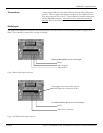
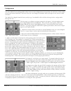
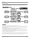
The SMR 821 provides a powerful external control option. This feature allows you to configure remote controls for the Master
Left/Right volume and the Channel 7/8 select function. The Remote connector provides a simple way to make these connec-
tions. NOTE: Use only shielded cable!
Refer to the illustrations below.
This example is used to control the Left/Right Master Volume
Control from a remote location with a simple connection on the
back of the unit. A 10k pot will provide approximately 0 to 30dB of
attenuation. A 100k pot will provide about 0 to 60dB of attenua-
tion. If desired, a control voltage can be inserted to “command”
attenuation instead of a pot. This voltage is inserted into the “C”
input and is positive referenced to SHD. NOTE: THE CONTROL
VOLTAGE SHOULD NEVER EXCEED 11 VOLTS DC.
Remote Channel 7/8 Select Connections
Shield (SHD)
Channel 7/8 Select (SEL)
Indicator LED Output (IND)
Figure 5. Remote Volume Control Connections