


ENGLISH
2
OVERVIEW
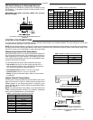
Front Panel
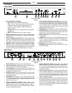
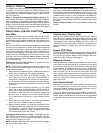
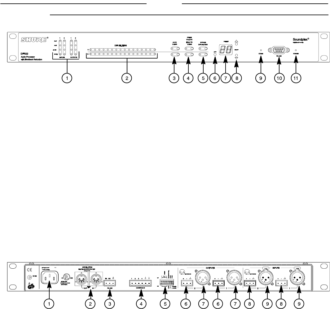
DFR22 FRONT PANEL
Figure 1
1. INPUT/OUTPUT Level Meters:
– CLIP. Illuminates at 3 dB below clipping level.
–0 VU.
+4 dBu, –10 dBV; software selectable. 0 dB is equal to
+4 dBu by default. If the input or output sensitivity is
changed to –10 dBV using the DFR22 software, 0 dB
equals –10 dBV.
– –20 dB. Illuminates when the signal meets or exceeds the
indicated level.
– MUTE. Illuminates when input or output is muted.
2. DFR Filter LEDs. Illuminate when individual feedback filters
are active. When a filter changes or is added, an LED flashes,
then stays on.
3. AUTO CLEAR Buttons and LEDs. Press and release these
buttons to configure Auto Clear mode for each channel. Press
them again to activate Auto Clear. When an Auto Clear LED
illuminates, Auto Clear is active on its corresponding channel.
4. PRESS TO LOCK / HOLD TO CLEAR Button and LEDs.
Press this button to lock filters at their current values. Holding
this button down will reset all feedback filters, even if they are
locked. The LED lights to indicate that the lock is active.
5. BYPASS DFR FILTERS Button and LEDs. Press these but-
tons to suspend feedback reducer operation and remove feed-
back filters from the audio path. When a Bypass LED illumi-
nates, feedback reduction is bypassed on the corresponding
channel. Bypass does not affect other processors (such as
equalizers, delay, limiters, etc.).
6. LOAD Button. Press this button to activate a selected preset.
7. PRESET Indicator. Shows the number of the currently active
preset. Blinks to show the number of the other presets in the
DFR22 when pressing the SELECT buttons.
8. SELECT Buttons. Press to scroll through the presets stored
in the DFR22.
9. COMM LED. Flashes in unison with the feedback filter LEDs
when the detector is deploying a new filter or changing an ex-
isting one, and also blinks whenever the unit is communicating
with a connected computer.
10. RS232 Port. Connects the DFR22 to a computer.
11. POWER LED. Illuminates when 100–240 VAC power is is ap-
plied to the DFR22.
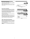
Back Panel
U.S. PATENT NO. 5,999,631
OTHER PATENT PROTECTION
APPLIED FOR
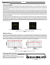
DFR22 REAR PANEL
Figure 2
1. Power Connector. Connects to 100–240 VAC power.
2. Shure Link Interface. Allows linking of up to 16 Shure Link de-
vices, which may be accessed by a computer.
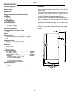
3. 3-Pin RS-232 Port. Connects the DFR22 to a computer. For
use with DFR22 software and control systems. Refer to the
Computer Connections section.
4. CONTROL IN Pins. Use control input pins for remote control
of preset switching, muting, and gain. Refer to the Control Pin
Connections section.
5. DIP Switches. Use Switches 1–4 to select a Shure Link De-
vice ID. Use Switch 5 to lock or unlock front panel controls. Re-
fer to the Front Panel Lockout section for information on lock-
ing front panel controls.
6. Output Connectors (Phoenix). These active, cross–
coupled, balanced outputs can be used with balanced or un-
balanced inputs. They can be switched between +4 dBu/–10
dBV line–level operation, using the DFR22 software. Refer to
the Audio Connections section.
7. Output Connectors ( XLR). These active, cross–coupled,
balanced outputs can be used with balanced or unbalanced in-
puts. They can be switched between +4 dBu/–10 dBV line–lev-
el operation using the DFR22 software. Refer to the Audio
Connections section.
8. Input Connectors (Phoenix). These active balanced inputs
can be used with balanced or unbalanced outputs. They can-
not be used simultaneously with an XLR connector for the
same input. They can be switched between +4 dBu/–10 dBV
line–level operation using the DFR22 software. Refer to the
Audio Connections section.
9. Input Connectors ( XLR). These active balanced inputs can
be used with balanced or unbalanced outputs. They cannot be
used simultaneously with a Phoenix connector for the same in-
put. They can be switched between +4 dBu/–10 dBV line–level
operation using the DFR22 software. See Audio Connections
section for more information.