


ENGLISH
7
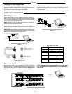
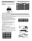
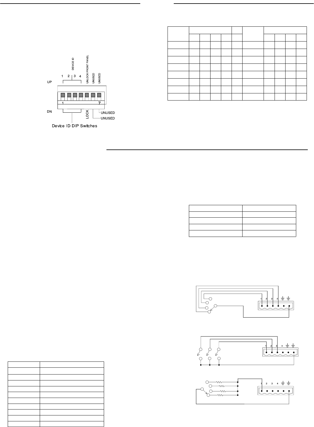
DIP Switch Settings for Networked Devices
Assign each Shure Link device a unique Device ID Number, using
DIP Switches 1–4, as shown in Figure 13. Refer to Table 2 for De-
vice ID settings.
IMPORTANT: Each Shure Link device MUST have a unique
Device ID number.
DIP SWITCH SETTINGS FOR NETWORKED DEVICES
Figure 13
Table 2. DEVICE ID SETTINGS
Device
DIP Switch
Device
DIP Switch
Device
ID
1 2 3 4
Device
ID
1 2 3 4
0 DN DN DN DN 8 DN DN DN UP
1 UP DN DN DN 9 UP DN DN UP
2 DN UP DN DN 10 DN UP DN UP
3 UP UP DN DN 11 UP UP DN UP
4 DN DN UP DN 12 DN DN UP UP
5 UP DN UP DN 13 UP DN UP UP
6 DN UP UP DN 14 DN UP UP UP
7 UP UP UP DN 15* UP UP UP UP
*Default setting.
CONTROL PIN CONNECTIONS
The control pins on the back of the DFR22 connect to switches, potentiometers, and controller hardware. The Control Input pins can be used
to change presets, adjust gain, and mute channels.
NOTE: Use the DFR22 software to configure the control pins so that they match the attached control hardware. You can also use the software
to assign minimum and maximum gain values for each control, as well as the gain increment for up/down volume control buttons. Refer to the
Control Pin section of the Online Help or to the Online User Guide.
Determining Control Pin Allocations
When allocating control pins, you should first determine which pins
are to be used for preset control. Any remaining pins can then be
used to adjust gain or to mute channels. The number of pins need-
ed for preset control depends on the type of control hardware used,
as well as the number of presets.
The following methods can be used to allocate control pins:
S One-to-One: Use one pin for each preset, starting at Pin 1,
and proceeding toward the right. You MUST use consecutive
pins. Connect momentary or latching switches.
S Shure DRS10 Switch: Use Pin 1 for up to 10 presets.
S Custom Switch: Use Pin 1 for up to 10 presets.
S Binary: Use the pin numbers listed in Table 3. Connect latch-
ing switches.
Table 3. BINARY CONTROL PIN ALLOCATION
Number of Presets
Pin Numbers
2 1
4 1 and 2
8 1–3
16 1–4
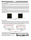
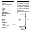
Preset Control Connections
Various types of control hardware can be connected to the Control
Input pins, as shown in Figure 14. When properly configured, the
DFR22 changes to the appropriate preset in response to the
switch. Resistor values for custom switches and the Shure DRS10
are listed in Table 4.
NOTE: The total resistance of the cable run, from the switch to the
DFR22, should be less than 100 ohms. Two-conductor, unshielded
cable, such as a Belden 8442, is recommended.
Table 4. CUSTOM SWITCH RESISTOR VALUES
PRESET RESISTOR VALUE
1
97 kΩ – ∞ Ω
2 44–60 kΩ
3 26–32 kΩ
4 17–20 kΩ
5 11.3–13.6 kΩ
6 7.8–9.3 kΩ
7 5.2–6.3 kΩ
8 3.3–4.1 kΩ
9 1.9–2.5 kΩ
10 0.63–1.1 kΩ
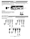
One-to-one Configuration
(Each pin represents one preset)
Binary Configuration
Shure DRS10 or Custom Switch Configuration*
WIRING CONTROL INPUT PINS FOR PRESET CONTROL
Figure 14