


ENGLISH
6
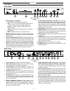
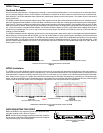
12 dB and 18 dB Output Pads
Each DFR22 output has a 12 dB pad and an 18 dB pad that can be
engaged through the software interface. Use these pads when con-
necting the DFR22 to lower-level inputs. They cannot be used to
prevent clipping at the output stage of the DFR22
NOTE: The Output meters indicate the signal level present at the
digital-to-analog converters. The 12 and 18 dB pads act upon the
signal after the digital-to-analog converters, so the meters do not
reflect the pads.
COMPUTER CONNECTIONS
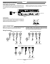
RS-232 Connections
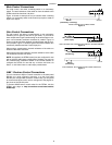
Connect the COM port on your computer to the 9-pin RS-232 con-
nector on the front panel of the DFR22, shown in Figure 9, using a
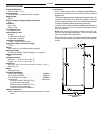
male-to-female serial cable. Pin outs for a 9–pin RS–232 cable are
shown in Figure 10 and listed in Table 1.
NOTE: Only the TX, RX, and GND pins need to be connected in
order to communicate with the DFR22.
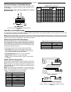
You can also connect a computer or control system to the 3–pin
RS-232 Phoenix connector on the back panel of the DFR22, as
shown in Figure 11.
IMPORTANT: You CANNOT connect two PCs to the DFR22 at the
same time. However, you CAN connect an AMX or Crestron sys-
tem and a PC to the DFR22 at the same time.
RS-232 SERIAL PORT CONNECTION
Figure 9
9-PIN FEMALE
TO COMPUTER
9-PIN MALE
TO DFR22
DFR22 9–PIN RS-232
FEMALE CONNECTOR
COMPUTER 9-PIN RS-232
MALE CONNECTOR
RS-232 CABLE PINOUTS
Figure 10
RS-232
PHOENIX RS-232 SERIAL PORT CONNECTION
Figure 11
Table 1. RS-232 PIN OUTS
DFR22 COMPUTER PIN NO.
–– –– 1
TX RX 2
RX TX 3
–– DTR 4
GND GND 5
–– DSR 6
–– RTS 7
–– CTS 8
–– –– 9
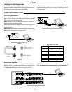
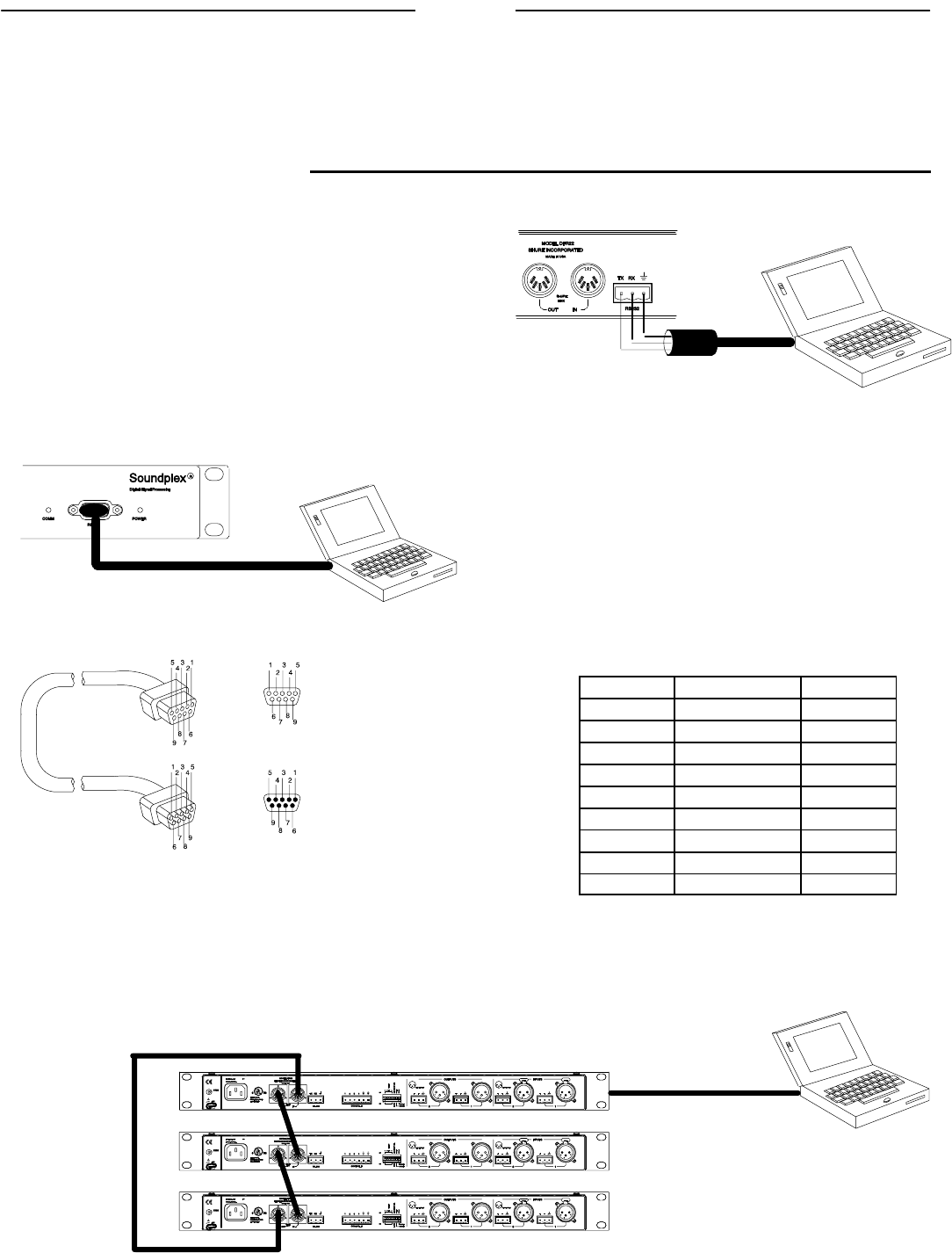
Shure Link Network
Up to 16 Shure Link devices, including the DFR22, DFR11EQ,
DP11EQ, P4800, and UA888, can be linked and controlled from
one computer. Using 5-pin DIN cables, connect the Shure Link IN
and Shure Link OUT of each device, as shown in Figure 12.
NOTE: The last device in the chain MUST be connected to the
first device (the one connected directly to the computer) to
form a loop.
SHURELINK OUT
SHURELINK IN
RS-232
DEVICE ID # 0
DEVICE ID # 1
DEVICE ID # 2
SHURELINK NETWORK CONNECTIONS
Figure 12