


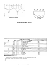
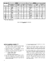
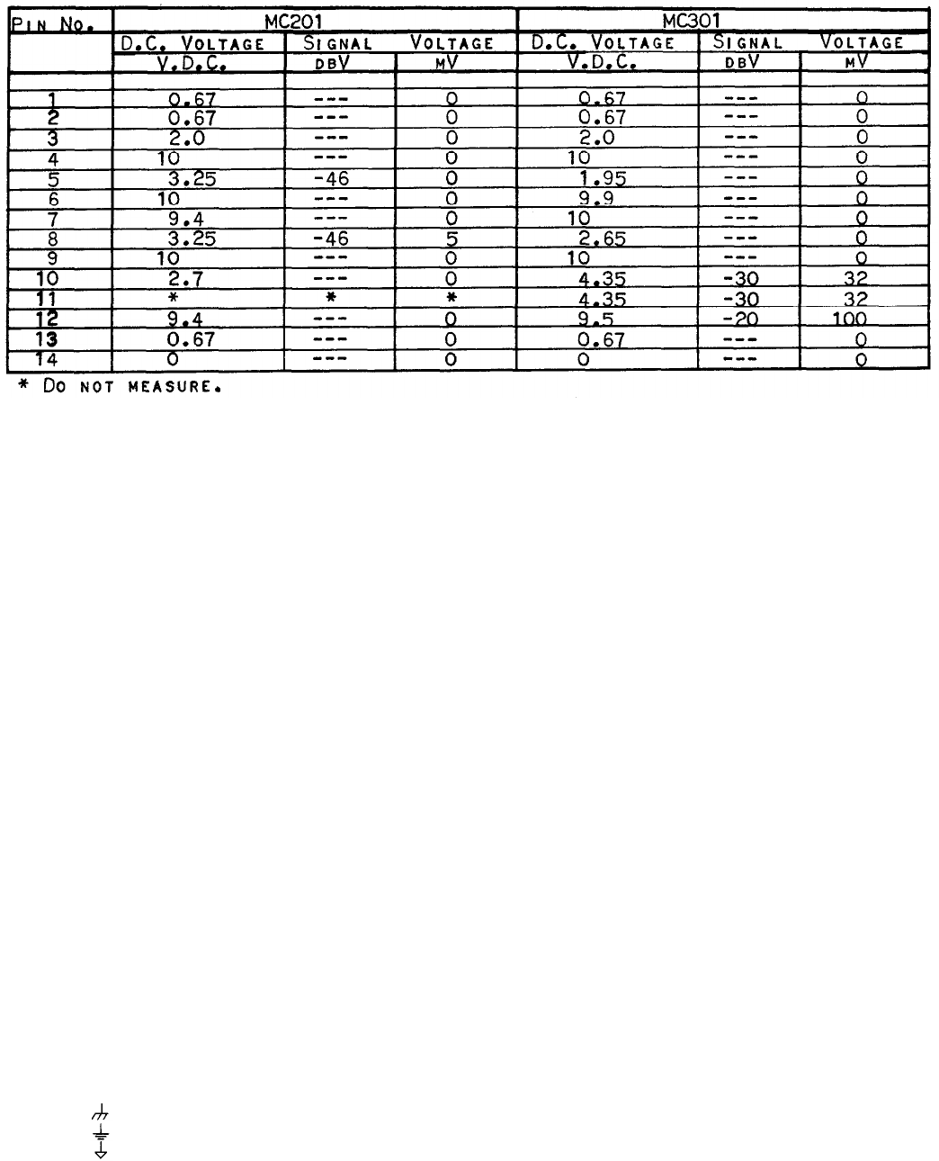
TEST VOLTAGES, INTEGRATED CIRCUITS
TABLE 1C
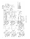
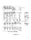
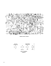
NOTES TO SCHEMATIC DIAGRAM AND
TEST VOLTAGES (Figure 4, Table 2)
1. All capacitors shown in microfarads and 50 volts or
more unless otherwise indicated. Electrolytic capac-
itors shown in mF X volts. pF = picofarad.
2. All fixed resistors ±10%, ¼ watt unless otherwise
shown. K = 1,000
M = 1,OOO,OOO
3. Components and wiring enclosed within dashed lines
are parts of printed circuit board assemblies.
4. The following symbols denote:
Direct chassis ground
Wired circuit ground
Printed circuit board ground
5. Arrows on potentiometers denote clockwise rotation.
6. Wire color designations with asterisks refer to
stranded No. 20 AWG wiring, and those in parentheses
refer to integral component leads. All other wires are
stranded No. 24 AWG.
7.
P. C. board terminals and wire destinations are shown
as board number-pin letter.
8. First digit of three-digit component references (for
example, R101) denotes number of printed circuit
board upon which part is mounted. One and two-digit
component references denote chassis-mounted parts.
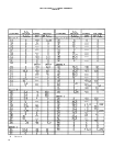
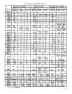
9. AC and DC voltages given in Tables 2A, 2B and 2C
are measured with a 2.2 megohm or greater AC volt-
meter and a 10 megohm or greater DC voltmeter. All
switches set as shown in schematic diagram. AC line
= 120 V, 60 Hz. Input 3 control set to 5, Input 1 and 2
controls set to zero, and Response Rate control set
to 3. Input signal 1 kHz applied to Input 3, level ad-
justed for 10 dB compression (signal at Pin A, board
3 equal to -30 dBV or 32 mV). Output control ad-
justed for + 4 dBm (+ 1.8 dBV or 1.23 V) line output
into a 600-ohm load.
20