


MODEL A100A CARRYING HANDLE ASSEMBLY
The Shure Model A100A Carrying Handle Assembly
provides a means for conveniently carrying the Shure
Model SE30 Gated Compressor/Mixer. The Model
A100A serves as a handle for carrying the SE30, as a
cover for the front panel, and as a tilt stand for position-
ing the SE30 at an angle for easy reading of the con-
trols and meters. The A100A is easily switched from
carrying handle use to tilt stand use simply by re-
adjusting two knurled bolts which secure the Model
A100A to the SE30. When in the tilt stand position,
the SE30 rests on rubber feet mounted on the Model
A100A. When in a carrying position, the SE30 may be
rested on any flat surface and is then protected by the
die cast corners on the rear of the case.
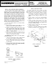
to mount the Model A100A on the Model SE30,
proceed as follows:
1. Place the back (bottom) of the SE30 on a flat
surface with the front controls facing up.
2. Position the Model A100A over the front of the
SE30. The top of the screw slots on the sides
of the Model A100A should align with the two
tapped holes (C) on the sides of the SE30. See
Figure 1, Carrying Position.
3. Screw the two knurled bolts supplied with the
Model A100A fully clockwise into the two tapped
holes (C) on each side of the SE30.
To position the Model A100A in tilt stand position,
proceed as follows:
1.
Loosen the knurled bolts at sides of Model A100A
by turning them partially counterclockwise.
2. Lift the Model A100A away from the SE30 so
that the knurled bolts pass through the bottom
of screw slots.
3. Swing the Model A100A handle beneath the SE30
and tighten the knurled nuts (screw clockwise).
See Figure 1 Position in Use.
MODEL A100B RACK PANEL
The Model A100B Rack Panel provides the Model
SE30 with supports for rack mounting. To mount the
Model A100B to the Model SE30, proceed as follows:
1.
2.
3.
4.
5.
Unscrew the four rubber feet from the bottom
of the SE30 to eliminate the obstruction of the
rubber feet when sliding the SE30 into a rack
panel.
Remove screws A and B (turn counterclockwise)
from each side of the SE30. See Figure 2, Rack
Panel.
Position the Model A100B brackets on the sides
of the SE30; the three holes of the rack panels
are to be aligned with the three tapped holes
A, B and C on sides of SE30.
Replace screws A and B (turn fully clockwise)
to fasten brackets to SE30.
Screw the ¼ inch bolts supplied with the Model
A100B fully clockwise into the tapped holes at C.
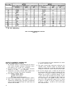
OVERALL DIMENSIONS
RACK PANEL
FIGURE 2
CARRYING POSITION
TILT STAND POSITION
CARRYING HANDLE ASSEMBLY
FIGURE 1
Copyright 1979, Shure Brothers Inc
27A865 (SK)
Printed In U.S.A.