


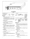
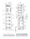
(25) AC Power Receptacle: Special internationally ac-
cepted connector for detachable ac line cord, three-
wire with safety ground pin.
(26) 30 Volts DC Jacks:
May be used for powering the
unit from an external 30 ± 20% dc source, or for
powering external equipment (up to 5 ma) from the
batteries or ac operated power supply of the SE30.
Controlled by front-panel Power switch (11) except
that an external load will discharge the batteries with
the unit OFF. In this case, remove the Battery Com-
partment (24) when unit is turned off.
(27) Voltage Selector Switch: Selects operating voltage
range of 108-132 V or 216-264 V (SE30-2E only).
GENERAL OPERATION
(See Figure 2)
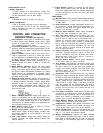
POWER CONNECTIONS:
AC Line Operation: Insert female end of ac line cord into
chassis power receptacle (25) and connect male plug to a
three-wire grounding ac power receptacle providing 108
to 132 V, 50/60 Hz (SE30 only). Model SE30-2E: Obtain
a suitable three-pin male plug and attach it to the line
cord. Plug should be installed by qualified service per-
sonnel. (Brown lead goes to “hot” or “live” terminal, blue
lead to neutral terminal, and green/yellow lead to ground
or earth terminal.) Select the proper operating voltage
(108-132 V or 216-264 V) using the voltage selector switch
(27). Insert female end of line cord into chassis power re-
ceptacle (25) and connect male plug to a three-wire
grounding ac power receptacle providing the proper ope-
rating voltage (108-132 V or 216-264 V, 50/60 Hz).
Battery Operation: Unit will automatically operate on bat-
teries installed in Battery Compartment (24) if unit is not
supplied with ac power. Condition of the 9-volt batteries
should be checked periodically with the Batt. Check Switch
(9) and batteries should be replaced as the meter indica-
tion approaches 0 VU with the unit in operation. Standby
battery condition may be checked even during ac line
operation, but an indication of +½ VU should be con-
sidered as the replacement point, since the battery voltage
will drop somewhat under load. The auxiliary light D cell
may be checked by operating the Aux. Light switch (10).
If the light becomes extremely dim, promptly replace or
remove the D cell to avoid damage due to leakage.
The unit will remain operative, except for the light, regard-
less of the condition of this cell.
Automatic Switchover: If batteries are installed in Battery
Compartment (24). operating power will be supplied by
these batteries in the event that the ac line voltage drops
too low or is removed. The switchover is automatic and
noiseless.
External DC Operation: An external source of dc may be
connected to the 30 Volts DC jacks (26) to operate the
unit if ac power is not used. The SE30 will draw approxi-
mately 12 ma. at 30 volts and must be operated at 30 volts
± 20%.
INPUT CONNECTIONS:
Microphones: Inputs (13) with switches (14) set to MIC.
are designed to accept signals from low impedance (25 to
600 ohms) dynamic, ribbon, or condenser microphones,
or microphone level signals such as the low impedance
microphone level output of a mixer. Inputs are balanced
(transformer coupled, mumetal shielded) and connections
are pins 2 and 3 “hot,” pin 1 ground. For unbalanced
sources, connect either pin 2 or pin 3 to ground at the
input cable connector.
High Level Signals: With switches (14) set to LINE the
inputs (13) will accept balanced 600-ohm line signals.
Inputs are bridging (with 66 K ohm impedance) so that
higher impedance sources such as Aux. signals (up to
33 K ohms) may also be used. For such unbalanced in-
puts, the signal may be applied to pin 3, with pins 1 and
2 ground. Input 1 can accept two high-level signals simul-
taneously through the three-pin Input connector (13a), and
through the Aux. Line Input jack (15), which are electrically
isolated but identical in gain and impedance.
OUTPUT CONNECTIONS:
Microphone: The microphone level output is available at
the Output connector (16) when the switch (17) set to MIC.
It is used for feeding a low-impedance microphone line
or the low impedance microphone input of an associated
piece of equipment. This is a balanced output with pin 1
ground and pins 2 and 3 “hot” and in phase with the cor-
responding input pins. This output is isolated and may be
used simultaneously with all other outputs appearing on
other connectors.
Line: The line output is available at the Output connector
(16) when the switch (17) is set to LINE, and at all times
at the Line Output terminals (20). These two connectors
are then wired in parallel and are provided for intercon-
nection convenience for either standard three-pin audio
connectors or for wires such as a telephone twisted pair.
This is a balanced output, transformer coupled with pin 1
ground and pins 2 and 3 “hot” and in phase with the cor-
responding input pins. The Line Output terminals (20) are
similarly numbered for phase indication. This output may
be used to drive impedances above 150 ohms but the VU
meter is properly calibrated for use with a 600-ohm termi-
nated line. The line output transformer will operate prop-
erly with up to 100 ma. flowing through the line, permitting
the use of ordinary “dialed-up” telephone lines with dc
across them. Operation at +4 dBm output is recommended
for this use to avoid any significant increase in distortion
due to overdriving the phone line. This output is isolated
and may be used simultaneously with all other outputs ex-
cept that the Output connector (16) and Line Output termi-
nals (20) are wired in parallel when the switch (17) is set to
LINE.
Aux. Output: An unbalanced output 20 dB below line level
is available at the Aux. Output jack (18) for a Separate,
isolated lower level feed. The impedance is 4.3 K ohms,
suitable for driving high impedance (10 K ohms or greater)
loads, such as reel to reel or cassette tape recorders or
power amplifiers. Tip of jack is in phase with tip of Aux.
Line Input jack (15).
Headphones: The headphone output appears on the rear
panel and is designated “Headphones.” A three-conductor
phone jack is used to provide a choice of level for different
sensitivity or impedance headphones. Normally, a two-con-
ductor phone plug should be used. If inserted only par-
tially (to the first detent), the available voltage is approxi-
mately .18 volts into 1,000 ohms with +4 dBm out of the
Line Output. With the same output conditions (+4 dBm),
the second position will provide approximately .38 volts.
These voltages are selected for normal operation with
600-ohm to 2,000-ohm headphones. Other headphone im-
pedances may be used, but with a variation in the head-
phone monitor level. The headphone jack is isolated from
the line output and with the headphone output shorted the
maximum change in line level output is .5 dB. If stereo
phones are used, the three-conductor plug may be inserted
completely (to second position) and output will appear in
both phones.
7