


GENERAL OPERATION (Cont’d)
The “Tip” connection of the headphone plug will be in
phase with Pin 3 of all Input (13) and Output (16) connec-
tors, and with the tip of the Mix Bus jack (12).
TYPICAL SET-UP AND OPERATION
A typical set-up and operation procedure is described
for remote amplifier applications, with a single input source
(microphone).
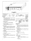
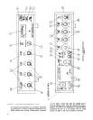
1. Connect microphone to Input 1 connector (13a) and
set Input switches (14) to MIC. Set Output Switch (17)
to LINE and connect phone line either to Output jack
(16) or Line Output terminals (20). Insert ac line cord
into ac receptacle (25) and plug cord into ac source,
unless battery operation is desired. Monitor head-
phones may be connected to Headphone jack (19).
2.
Set Compressor (22) and Gated Memory (21) switches
to ON, Meter switch (8) to DB COMP, Lo-Cut switches
(2) and VU Range switch (4) as appropriate.
3. Rotate Input Control (1) and Output Control (3) full
counterclockwise to 0, and set Response Rate Control
(6) to 3, assuming a typical speech input.
4. Turn Power switch (11) ON and wait approximately 1
minute for the circuitry to stabilize. DB Comp. meter (7)
should read full scale left (line below zero on lower
scale) and Gated Memory indicator (5) should be red.
5.
Set Input 1 switch (2a) to TONE OSC. and rotate Input
1 Control (la) clockwise for a DB Compression meter
(7) reading of 10 (lower scale). Gated Memory indi-
cator (5) will change to white.
6. Set Meter switch (8) to VU and rotate Output Control
(3) for a VU meter (7) reading of 0 VU (upper scale).
Tone will be heard in headphones. The signal thus ap-
plied to the line may be used for calibration of the
equipment receiving the signal.
7. Reduce setting of the Output control (3) for a meter
reading of -2 VU, and return Input 1 switch (2a) to
IN. Note setting of Output Control (3) for future use.
(This reduction in sine-wave output is made to account
for the moderate short-term output dynamic range en-
countered for speech with the suggested Response
Rate control setting. A faster setting would eliminate
the need for this, but the compression would then be-
come more audible.)
8. Set Meter switch (8) to DB COMP.
9. Now, with the expected average sound level entering
the microphone, set the Input 1 control (la) for an
average DB Compression meter (7) reading of ap-
proximately 10 (lower scale). This is the recommended
operating level for the SE30, since the unit will now
be able to maintain a substantially constant output
level for input reductions of 10 dB and increases of
as much as 30 dB.
10. Observe the operation of the Gated Memory indicator
(5). It should be white during speech input and change
to red during pauses between sentences and words,
indicating that the DB compression level is being
“remembered” during program lapses.
If the indicator remains white or “jitters” with no
spoken input to the microphone, it is an indication
that the acoustic background noise level at the micro-
phone is near or above the Gated Memory threshold.
The solution to this is to reduce the setting of the
Input 1 Control (1a) until the Gated Memory Indicator
(5) is consistently red without speaking into the micro-
phone. The DB Compression level will then be deter-
mined by the loudness of the speaker and his proximity
to the microphone. This adjustment is very important
to insure proper operation in situations having very
high background noise levels, such as sporting events
or parades.
OPERATING CONSIDERATIONS
LARGE CHANGES IN INPUT LEVEL
If the overall sound and noise levels entering the micro-
phone do not significantly change from those encountered
during set-up, as indicated by a DB Compression meter
(7) reading of 0 to 20 dB, and if proper operation of the
Gated Memory indicator (15) continues, it will not be neces-
sary to adjust any controls further.
If, however, large changes in the signal going into the
microphone and/or in background noise do occur, some
Input 1 control (1A) readjustment may be advisable, as
indicated by the DB Compression meter and Gated Mem-
ory indicator. For example, a significant increase in back-
ground noise and signal may occur during an exciting por-
tion of a sporting event, such that the Gated Memory no
longer “holds” during pauses and the DB Compression
reads higher than previously indicated. A gradual reduc-
tion of the Input 1 control (1a) setting will not be noticeable
to the listener, due to the automatic effect of the compres-
sor, but proper action will be restored.
During a later, more subdued portion of the program, it
may become apparent that the DB Compression meter (7)
is reading near zero, and the Gated Memory indicator does
not always change to white during speaking. A gradual
increase of the Input 1 control (la) setting will then allow
operation at the proper level. Thus, during operation, after
setting the proper output level with the master gain control,
it is generally necessary only to monitor compression level
on the DB Compression meter (7) and to observe proper
action of the Gated Memory indicator (5).
Control setting changes need only be made for long-
term, large changes in signal or noise levels. It is not nec-
essary to “ride gain” to maintain a constant line output
level as measured by the VU meter, since that is the com-
pressor’s function.
RESPONSE RATE ADJUSTMENT
The proper setting of the Response Rate control (6)
is determined by subjective factors, according to the type
of program material. Generally, a slower setting will result
in less audible compression, but a wider short-term out-
put dynamic range, that is, a less consistent output level.
Faster settings will result in a more nearly constant output
level but will make the effect of compression more audible.
The Response Rate control (6) setting may be changed
during operation for more satisfactory results if desired. A
guideline for an initial setting according to program mate-
rial is: Speech-3; Popular Music-5; Symphonic Music-
7. The output leveling effect may be observed for various
settings by observing the VU meter (Meter switch (8) set to
VU), while the subjective effect is best ascertained by
listening on monitor headphones.
MULTIPLE INPUTS
Up to three microphones or input sources may be used
simultaneously with the SE30. In this case, the overall
“mixed” signal and background noise levels determine
DB Compression and Gated Memory action. For the best
results when several inputs are to be used one at a time,
only the used Input controls should be turned up. For a
8