


SERVICE INSTRUCTIONS
The SE30 Gated Compressor/Mixer uses components
of the highest quality, operating well within their ratings
to assure long life and excellent stability. No routine main-
tenance is necessary with the exception of battery re-
placement.
CAUTION:
There are no user serviceable parts within the
case of the SE30. Refer servicing to qualified
service personnel.
BATTERY REPLACEMENT:
No special tools are required.
1.
2.
3.
4.
5.
Turn knob on back of Battery Compartment (24) ¼
turn counterclockwise to OPEN position.
Slide compartment rearward out of chassis.
Release cover by unscrewing thumbscrew on top of
cover.
Tilt cover upwards, pivoting at connector end of com-
partment, thus exposing batteries.
Unsnap the six 9-volt batteries and replace. Remove
the 1.5-volt D cell and replace.
Note: The SE30 may be operated in an emergency
with only three 9-volt batteries, installed in
either the right or left row of battery connectors.
The 1.5-volt D cell operates only the auxiliary
light, and may be omitted if this feature is not
required.
6.
Pivot cover down, align thumbscrew with speednut,
and tighten fully. Batteries are now held firmly by pads
in cover.
7.
Align metal bottom plate of compartment with plastic
guides in SE30 chassis and gently slide compartment
fully into chassis.
8.
Rotate knob clockwise to LOCK position.
COVER REMOVAL AND REPLACEMENT
Most servicing and calibration can be performed with
only the top cover removed. The only tool required is a
No. 1 or No. 2 Phillips screwdriver.
1.
2.
3.
Turn Power switch (11) OFF and remove ac line cord
from AC Power Receptacle (25).
Remove the upper of the two Phillips screws on each
side of the SE30.
4.
5.
6.
7.
Remove the top cover by grasping the upper half of
each side and pulling straight up. This exposes the
components shown in the top view of Figure 5.
End plates may be removed for easier access to side-
mounted components by removing the remaining Phil-
lips screws on each side of the SE30. The end plates
may then be removed by pulling straight up.
The bottom cover may be removed either with or with-
out removing the end plates as above. Invert the SE30
and unscrew the four bumpers (feet). The bottom cover
may then be pulled straight up from the central
chassis. The SE30 will operate properly, except for
possible increased hum pickup, with both the top and
bottom covers removed.
Replace the bottom cover by placing the chassis up-
side-down and sliding the cover over the chassis,
securing it in place with the four bumpers and screws.
If the end plates are attached to the cover, position it
so that the large holes in the end plates are near the
front of the chassis.
Replace each end plate, if necessary, by sliding it
between the end of the chassis and the inside of the
bottom cover, securing it with a Phillips screw. Posi-
tion the large hole near the front of the chassis. The
right and left end plates are interchangeable.
8. Replace the top cover by sliding the ends downward,
guided by the recesses in the end plates. Secure with
the two remaining Phillips screws.
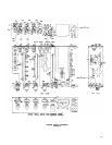
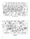
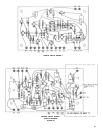
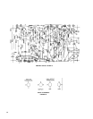
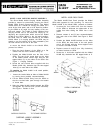
CHASSIS PARTS
Figure 5 illustrates the location of each chassis-mounted
component by reference number, corresponding with those
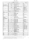
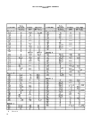
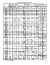
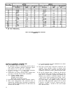
in the Schematic Diagrams (Figure 4) and Replacement
Parts List (Table 1). Note that all one and two-digit refer-
ence numbers denote ‘chassis-mounted components.
The five printed circuit boards are numbered 1 through
5 from left to right, and are easily removable as outlined
below. Trimmer potentiometers used during calibration
are located on P.C. Boards 2 and 3 and are shown in Figure
5. Complete replacement P.C. Board Assemblies are avail-
able. See Replacement Parts List (Table 1), and note that
the replacement of certain components and P.C. Boards
will necessitate recalibration of the unit.
The color-coded chassis wiring is indicated both in the
Schematic Diagrams (Figure 4) and in the P.C. Board Parts
Placement Diagrams (Figure 6). Connections associated
with each printed circuit board are shown in the Schematic
Diagram as follows:
PC. Board 1, Figure 4A; P.C. Board 2 and P.C. Board 3,
Figure 4B; P.C. Board 4, Figure 4C; and P.C. Board 5,
Figures 4C and 4D. Power supply wiring is shown in
Figure 4D.
LAMP REPLACEMENT
The tools required are a No. 1 or No. 2 Phillips screw-
driver, and ¼" and 5/16" open-end wrenches.
1.
2.
3.
4.
5.
6.
7.
8.
Remove the topcover as described above.
To replace the ac operated pilot lamps (PL1 and
PL2), remove the hexagonal-head screws mounting
the lampholders to their vertical brackets, using the
¼" open-end wrench.
The sockets may now be pulled rearward and rotated
up so that the #47 bulbs may be replaced. It is advis-
able to replace both of these lamps when one burns
out.
Replace the sockets in position and secure with the
hexagonal head screws. Note that there are two holes
in each bracket, the rear hole for the socket tab and
the front hole for the screw.
To replace the battery operated Aux. Light (PL3), note
the position of the socket between the Gated Memory
indicator (M2) and the meter (M1). Remove the hex
nut and lockwasher holding the socket to the left
meter stud, using the 5/16" open-end wrench.
Unscrew the bulb and replace with a #223 lamp,
tightening it firmly in the socket.
Position the socket bracket over the meter stud, fol-
lowed by the lockwasher and the nut, and tighten
while holding the socket in proper position.
Replace the top cover.
PRINTED CIRCUIT BOARD REMOVAL AND SERVICE
A standard blade screwdriver or similar prying tool and
long-nose pliers are the only tools needed, unless sol-
dered components are to be replaced. To avoid component
and printed circuit board damage, a soldering iron of 40
watts or less is recommended
1. Remove AC line cord and remove top cover as de-
scribed above.
2. Each printed circuit board is mounted by four plastic
25