


33
Parts Identification
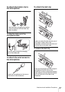
i OUTPUT (audio output) connector
(3.5-mm diameter stereo mini jack)
Connect one end of the supplied XLR-BMP
conversion output cable for the URX-P2 or
the stereo mini plug-BMP conversion cable
here and the other end to the microphone
input on a camcorder, mixer, or amplifier. If
the microphone input connector on the
device connected to the tuner is a stereo
mini jack, connect the straight (BMP) plug
to the tuner and the L-shaped (stereo mini)
plug to the microphone input connector on
the device.
To prevent damaging the tuner, do not
apply power voltage to this connector
through the connection to external devices.
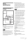
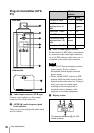
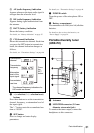
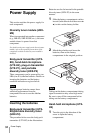
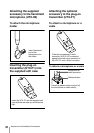
Diversity tuner module
(URX-M2)
a SET button
Press to change and enter display
parameters.
For details, see “Tuner Settings” on page 42.
b RF (radio frequency) indicator
The color indicates the strength of the RF
input signal.
On (green): RF input is 25 dBµ
1)
or more.
Off: RF input is less than 25 dBµ
1)
.
1) 0 dBµ = 1 µVEMF
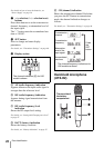
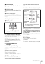
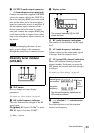
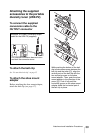
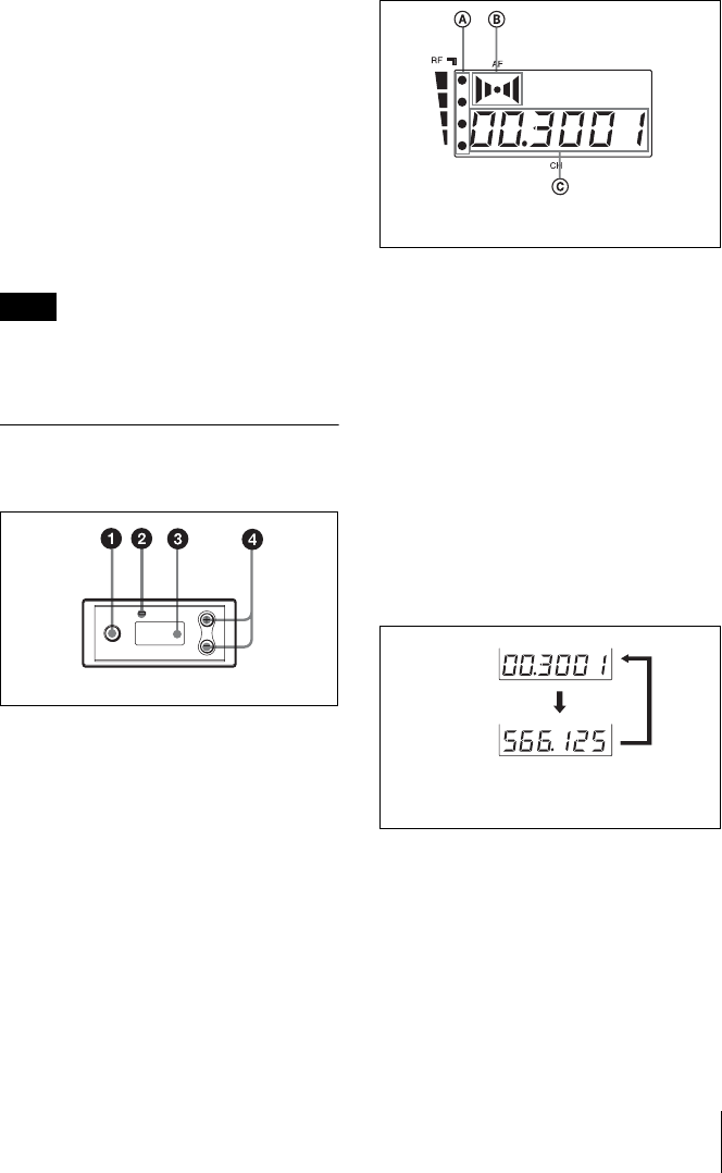
c Display section
A RF (radio frequency) indications
The number of dots indicates the RF input
level.
B AF (audio frequency) indication
Appears whenever the output audio signal
is stronger than the reference level.
C GP (group)/CH (channel) indication
Shows the reception channel group and
channel number. Each time you press the
SET button, the channel indication changes
as follows.
For details, see“Tuner Settings” on page 42.
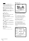
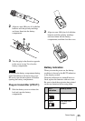
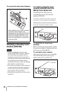
d + (+ selection) / – (– selection/reset)
buttons
Press these buttons to set the reception
channel and frequency.
Note
The channel indication (C) for U30
model is shown.
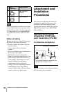
Reception
channel group
and number
Reception
frequency
The channel/frequency indications for
U30 model are shown.
Press
the
SET
button.