


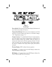

Displays
The 7 Segment LED channel display already mentioned (00 to 99).
2. A 5 segment LED light array for AF, that aids in setting micro-
phone gains and monitoring receiver microphone and line level
outputs. Light numbers 4 and 5 have a Peak Hold feature.
3. A 5 segment LED light array for RF, that aids in checking the
transmitter and monitoring for the possibility of initial interfer-
ence.
4. A 2 segment LED array that indicates diversity action and antenna
configuration.
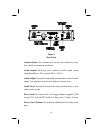
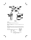
Audio Output
An XLR type connector is located on the rear panel that provides
either line level audio or microphone level audio output, which is
controlled by a slide type switch also located on the rear pane. The
output level is adjustable with a screwdriver accessible potentiometer
located on the rear panel.
Power
The USR-100 will operate from the supplied AC adapter or any
nominal 12-15 volt AC/DC 600 mA supply.
Audio
The USR-100 audio circuitry is designed to complement the trans-
mitter audio. A compandor circuit is utilized to enhance the dynamic
range. A slow turn-on circuit prevents the audio output stage from
passing noise spikes present during receiver power up conditions.
-3-