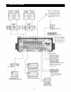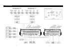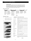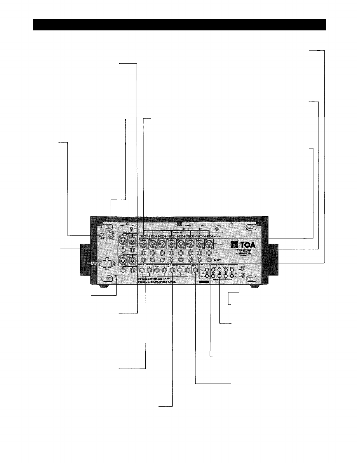
Rear Panel (RX-208)
RX-208
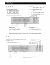
Program Line Output Connectors and Jacks
(LINE OUT, PGM L, R)
These connectors and jacks are the outputs
of the console deriving the signals after each
program master fader. The XLR connectors
are balanced, transformer-isolated, floating,
with an output impedance and nominal level
of 600 ohms and +4dB, respectively. The
phone jacks are unbalanced, with an output
impedance and nominal level of 600 ohms
and +4dB, respectively.
Power Switch (POWER)
This switch provides AC power to the
console. Power should only be applied after
all audio connections have been completed.
Power Fuse
Phantom Power Switches
(PHANTOM 1~8)
The phantom power switch on
each input channel permits the
user to supply 48V DC through
the input connectors to a con-
denser microphone. If phantom
power is not required, the
switch must be in the "off" posi-
tion.
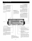
Accessory Send/Receive Jacks
(ACCESSORY 1~8)
These jacks are provided as patching points
for inserting signal processing equipment
such as compressor/limiters, noise gate, etc.
An output impedance of the accessory send
and an input impedance of the accessory
receive are 10k ohms. Both nominal signals
levels are 0dB. Please refer to the detailed
explanation on page 11.
Channel Input, Unbalanced Jacks
(CHANNEL IN UN-BAL 1~8)
These 8 standard 1/4" phone jacks are
unbalanced with an input level of —30dB and
input impedance of 10k ohms. They will
accept low or high impedance sources. When
plugs are inserted into these jacks, the input
level switch must be set to the "UN-BAL"
position.
Channel Input, Balanced Connectors
(CHANNEL IN BAL 1~8)
The XLR connectors are balanced, trans-
former-isolated, floating, with an input im-
pedance of 600 ohms, and will accept low im-
pedance microphones as well as other im-
pedance sources. When the XLR connectors
are employed, the input level switch on the
front panel must be set at the "BAL" posi-
tions. Proper adjustment of both input level
switch and trim control make it possible to
provide the optimum setting for each input.
Power Cord
Ground Terminal (GND)
The chassis must be grounded.
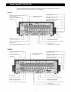
Foldback Line Output Connectors and Jacks
(LINE OUT FB 1, 2)
These connectors and jacks are the foldback
outputs deriving the signals after each
foldback master fader. The XLR connectors
are balanced, transformer-isolated, floating,
with an output impedance and nominal level
of 600 ohms and +4dB, respectively. The
phone jacks are unbalanced, with an output
impedance and nominal level of 600 ohms
and +4dB, respectively.
Echo Output Jacks (ECHO SEND)
These jacks are unbalanced, with an output
impedance of 600 ohms. One jack is for +4dB
output and the other is for —20dB output. The
jacks are provided for connection to external
echo machines. The +4dB jack can be used for
output cascading.
Sub Input Jacks
(SUB IN PGM L, R, FB 1 , 2, ECHO)
These five jacks are directly connected to the
corresponding mixing busses (program L, R,
FB1, 2, and echo), and are provided for
cascade connection to expand the input
capacity.
Ground Terminals (GND)
These may be used to provide ground connection
for tape decks or turntables.
Stereo Input Pin Jacks (STEREO IN 1, 2)
Each stereo input has both AUX input and
PHONO input pin jacks that are switchable on the
front panel. RIAA equalization is provided on the
phono input for accepting turntables with
magnetic cartridges.
Recording Output Pin Jacks
(REC
OUT,
PGM L, R)
The jacks are unbalanced and provide pre-graphic
EQ, pre-program fader signals for connection to
tape recorders.
Auxiliary Echo Input Jack (AUX ECHO IN)
This standard phone jack is unbalanced and
accepts low or high impedance sources at nominal
—20dB level. The jack sends an echo or reverb
return signal directly to the program L and R
mixing busses. Inserting a plug in the jack
interrupts the return signal from the built-in echo
unit. The echo or reverb return signal can be
controlled by the echo return volume on the front
panel.
– 6 –


